In this tutorial we investigate shear stresses induced in a beam by bending.
Analysis of shear bending stress is more complex than normal bending stress and this tutorial provides a basic introduction valid for beams of rectangular cross-section with height significantly greater than breadth.
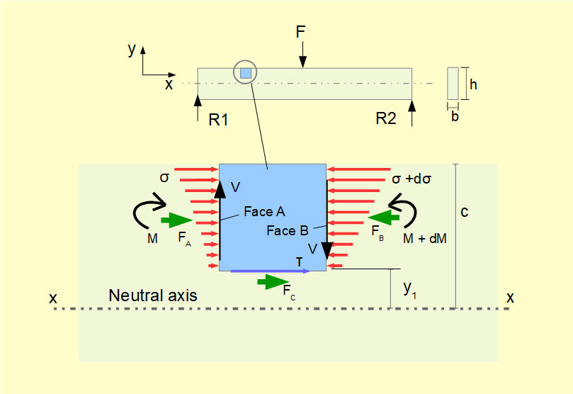
The diagram below illustrates the origin of shear stress in bending.

The diagram shows a beam of rectangular cross-section with height h and width b.
A small element of the beam height y1 above the neutral axis x-x with vertical faces A and B is subject to shearing forces V. The bending moment M varies along the beam and from our previous study we know:

Also from our study of normal bending stress we know σ is directly proportional to M.

It follows that the mean normal stress on face B must be greater than on face A and thus the net the force FB on face B must be greater than the net force FA on face A.
For the element to be in equilibrium the sum of horizontal forces must equal zero. Thus a horizontal force FC is exerted on the bottom face of the element resulting in a shear stress τ on this face.

Note that Iz is the second moment of area of the entire cross-section about the neutral z axis.


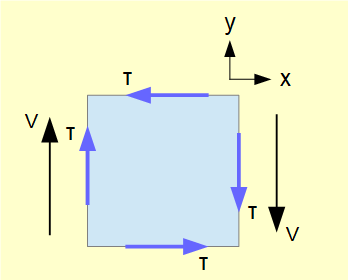
We know that the shear stress on a plane in a biaxial element is accompanied by shear stresses of equal magnitude on the other three orthogonal planes with directions such that the element is in equilibrium. Hence a shear stress of the same magnitude exists on the other faces of the element as shown below.
(In this model it was assumed that V has the same value on both vertical faces of the element, which is true for beams with point loading. For distributed loads, V is not constant but when the length of the element → 0 the expression above for τ is valid.)

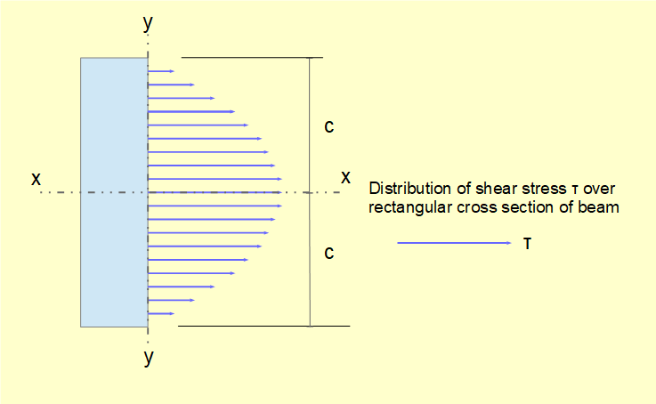
We now examine the distribution of shear stress on the cross-sectional y-z plane in the case of the rectangular section below.


Distribution of τ across the section for values of y1 from -c to +c is a quadratic function as shown below. τmax occurs at the neutral axis where y1 = 0 and τ = 0 where y1 = ±c. Note that locations of minimum and maximum shear bending stresses are the reverse of normal bending stresses.


Compare this value with the assumption of uniformly distributed shear stress over the cross-section for shearing force V giving:

i.e. τmax is greater by a factor of 3/2. Similar factors for solid circular and hollow circular sections are 4/3 and 2 respectively.
Next: Deflection of beams in bending
I welcome feedback at: