In this tutorial we will:
- calculate shearing forces (V) and bending moments (M) for a simply supported beam with point loads
- establish the general relationship between V and M for this configuration of load
- construct shearing force and bending moment diagrams
Consider this example of a simply supported beam with three point loads. In the co-ordinate system x = 0 at the left hand end.
Reactions R1 and R2 are calculated as follows.
Σ vertical forces = 0
upward forces are +ve
Gives: R1 + R2 - 2 - 8 - 6 = 0 Thus R1 + R2 = 16 kN --------- (i)
Σ of moments about left hand end = 0
Clockwise moments are +ve
Gives: (2 x 2) + (8 x 4) + (6 x 6) - (R2 x 8) = 0
Thus: (8 x R2) = 4 +32 +36 = 72 Gives: R2 = 9 kN
Substitute R2 in (i) Gives: R1 = 7 kN
We now calculate shearing forces V and bending moments M along the beam using free body diagrams from datum x = 0 at the left hand end.
Note that M = 0 at x = 0 and at x = 8 (points of simple support cannot sustain bending moments).
Now consider free body diagrams for sections of the beam between each point load, say at x=1, x=3. x=5, x=7 and take Σ vertical forces = 0 and Σ moments = 0 for each section.
Firstly consider the section from x = 0 to x = 1. Assume that we do not know the signs of V and M.
Σ vertical forces = 0
±V + 7 = 0 Thus according to the sign convention for direction of external forces, V appears to be = -7 kN
However, the sign convention for shearing forces on an element of the beam is:
We must reverse the sign of V so in this case V is +ve. Thus: V = + 7 kN
It is also clear from the free body diagram that V has the same value when 0 < x < 2.
Σ moments = 0 (at position x = 1)
(R1 x 1) ± M = 0
Gives ( 7 x 1) ± M = 0 Thus according to the sign convention for direction of moments, M appears to be = -7 kNm
However, the sign convention for +ve and -ve bending moments on an element of the beam is:
We must reverse the sign of M so in this case M is +ve. Thus: M = +7 kNm
The free body diagram is as follows showing +ve bending and +ve shear.
Note that the conflict regarding sign conventions for V and M can be avoided if the direction of the x axis is reversed and the datum point for taking sections is from the right hand end of the beam. On balance I prefer using the conventional direction for the x axis.
By the same method free body diagrams for sections of the beam from x = 0 to x = 3, x = 5 and x = 7 are obtained as follows.
At x = 3: V = 5 kN M = 19 kNm
At x = 5: V = -3 kN M = 21 kNm (note V changes sign from + to - )
At x = 7 V = -9 kN M = 9kNm
it can be seen from the above free body diagrams that V is constant between points where a loading or reaction force is applied, i.e.
for 0 < x < 2 V = 7 kN
for 2 < x < 4 V = 5 kN
for 4 < x < 6 V = -3 kN
for 6 < x < 8 V = -9 kN
At the locations of point loads and reaction forces V is indeterminate, i.e. there is a step change.
We plot values for V on a shearing force diagram.
Before we construct the equivalent bending moment diagram consider the changes in M and values of V for sections along the beam.
By calculation:
at x = 0 M = 0 kNm
at x = 1 M = 7 kNm
at x = 2 M = 14 kNm
at x = 3 M = 19 kNm
at x = 4 M = 24 kNm
at x = 5 M = 21 kNm
at x = 6 M = 18 kNm
at x = 7 M = 9 kNm
at x = 8 M = 0 kNm
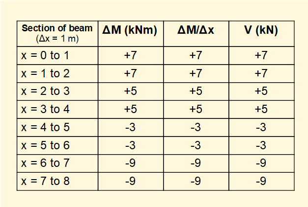
which applies to each interval Δx between points where loads are applied.
We can now construct the bending moment diagram for the beam in this example noting that the slope of M is constant between the point loads and equals V (as shown in the above table).
We will develop the relationship between V and M in more general terms in the next tutorial.
Next: Beams - bending moments and shearing forces - cantilever with uniform distributed load
I welcome feedback at: