In this tutorial we will:
- investigate shearing forces and bending moments for a simply supported beam with a variable distributed load w = f(x) using the relationships between V, M and w established in the previous tutorial.
- construct the shearing force and bending moment diagrams
In previous tutorials for a simply supported beam with point loads and a cantilever beam with uniform distributed load we developed the shearing force and bending moment diagrams by calculating V and M at specific points x along the beam from first principles using free body diagrams.
For this configuration of load we express V and M as mathematical functions of x from which we can obtain V and M at any point x along the beam.
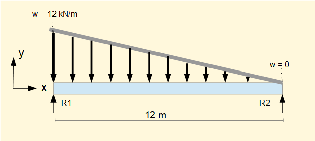
Consider this example of a simply supported beam 12 m long with variable distributed load w. The load is a linear distribution from w = 12 kN/m at x = 0 to w = 0 at x = 12.

The first step is to express w as a function of x, in this case a linear function with slope = -1 and intercept on the y axis (equivalent to the w axis) = 12.
This represents the linear function: w = (12 - x)
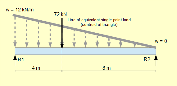
Next step is to find the equivalent total load and its point of application. We derive the equivalent total load through the following integral.


This load acts at a point through the centroid of the load triangle which is 1/3 from the base of the triangle at the LH end (a centroid position can also be computed for non-linear load functions).

Reaction forces R1 and R2 are then determined using Σ forces = 0 and Σ moments = 0.
Σ forces = 0 gives: R1 + R2 = 72 --------- (i)
Σ moments = 0 at x = 0 gives: (72 x 4) - (R2 x 12 ) = 0
gives: R2 = 24 kN
Substitute R2 in (i) gives: R1 = 48 kN
Next we determine the function for the shearing force V(x) from the indefinite integral established in the previous tutorial:


To find the constant of integration C consider V(x) at x = 0:
Substituting x = 0 in V(x) gives: V(0) = C
We know V(0) = R1 = 48 kN Thus C = 48

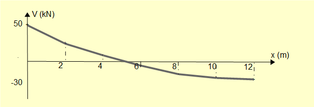
Calculated values of V and the corresponding shearing force diagram are shown below. The diagram plots V at x = 0, x = 2, x = 4, x = 6, x = 8, x = 10 and x = 12 . The true curve is a continuous quadratic function.
| x(m) | 0 | 1 | 2 | 3 | 4 | 5 | 6 | 7 | 8 | 9 | 10 | 11 | 12 |
|---|---|---|---|---|---|---|---|---|---|---|---|---|---|
| V(kN) | 48 | 36.5 | 26 | 16.5 | 8 | 0.5 | -6 | -11.5 | -16 | -19.5 | -22 | -23.5 | -24 |


for which the solution is x = 5.06
To obtain a function M(x) for the bending moment we use the relationship established in the previous tutorial:


To find the constant of integration C consider M(x) at x = 0
Substituting x = 0 in M(x) gives: M(0) = C
We know M(0) = 0 Thus C = 0
Computed values of M (rounded to integers) for integer values of x and the corresponding approximated bending moment diagram are shown below. The true curve is a continuous third order function of x.
| x(m) | 0 | 1 | 2 | 3 | 4 | 5 | 6 | 7 | 8 | 9 | 10 | 11 | 12 |
|---|---|---|---|---|---|---|---|---|---|---|---|---|---|
| M(kNm) | 0 | 42 | 73 | 95 | 107 | 111 | 108 | 99 | 86 | 68 | 47 | 24 | -0 |


it follows that the maximum value of M(x) occurs where V(x) = 0 (x = 5.06)
This and the previous two tutorials have examined shearing forces and bending moments for three specific configurations of support and loading of a beam, viz.
- simply supported beam with point loads
- cantilever (beam with single fixed support) with uniform distributed load
- simply supported beam with variable distributed load
The methods of analysis demonstrated can be applied to beams with other combinations of support and loading. General formulae for shearing force and bending moment for the most common configurations are found in text books and online.
Next: Bending moments and shearing forces in beams - singularity functions
I welcome feedback at: