In this tutorial we will:
- investigate shearing forces and bending moments for a cantilever beam with uniformly distributed load w
- establish a general relationship between shearing force V, bending moment M and load w
- construct shearing force and bending moment diagrams
Consider this example of a cantilever beam 8 m long with uniform distributed load w = 1 kN/m. In the equilibrium state load forces and moments are balanced by a reaction force R1 and reaction moment Mre acting at the left hand support. Note the anti-clockwise direction of Mre is opposite to the clockwise direction of the moment produced by load w.
A uniform distributed load is equivalent to a point load at the load centre. In this case the load centre is the centroid of a rectangle in the x-y plane.
The equivalent point load is (8 m) x (1 kN/m) = 8 kN
Reaction force R1 and reaction moment Mre are calculated by Σ forces = 0 and Σ moments = 0.
Σ forces = 0 (upward forces +ve)
R1 - 8 = 0 Thus: R1 = 8 kN
Σ moments = 0 (take moments about the fixed support at the left hand end - clockwise moments +ve)
Mre + (8 x 4) = 0 Thus: Mre = -32 kNm (anti-clockwise moment)
I have been a bit pedantic here regarding signs. Because there are only two terms in each equilibrium equation it is obvious that the unknown terms (R1 and Mre) are opposite in sign to the known terms. This is not the case for equations where there are multiple terms and signs for unknown terms are only revealed by the solution. To avoid errors in signs always state unknown quantities as positive in the initial equations.
Now calculate shearing forces V and bending moments M along the beam using free body diagrams from datum x = 0.
Firstly consider points x = 0 and x = 8
At x = 0 there is a step change from V = 0 to V = |8| kN (absolute value). The mode of shear at the fixed support is +ve thus V = +8 kN. The absolute value of the bending moment M at the fixed support is |32| kNm, equal to reaction moment Mre. The mode of bending is negative thus M = -32 kNm.
At x = 8 (the right hand end of the beam) shear force and bending moment cannot be sustained by a reaction force or reaction moment thus V = 0 and M = 0
Now consider, say, free body diagrams for sections of the beam from x = 0 to x = 2, x = 4, and x = 6 and take Σ forces = 0 and Σ moments = 0 at these points.
Assume that we do not know the signs of V and M.
Σ forces = 0
8 -2 + V = 0 Thus V = -6 kNm but change sign according to convention.
Thus V = 6 kN
Σ moments = 0
(8 x 2) - (2 x 1) -32 + M = 0 thus M = +18 kNm but change sign according to convention.
Thus M = -18 kNm
The free body diagram is as follows showing negative bending and positive shear.
Sections at x = 4 and x = 6 follow below. Values of V and M using Σ forces = 0 and Σ moments = 0 are easily computed.
V = 4 kN M = -8 kNm
V = 2 kN M = -2 kNm
The above values for V and M plus calculated values for additional sections at x = 1, x = 3, x = 5 and x = 7 are tabulated below.
| x(m) | V(kN) | M(kNm) |
|---|---|---|
| 0 | 8 | -32 |
| 1 | 7 | -24.5 |
| 2 | 6 | -18 |
| 3 | 5 | -12.5 |
| 4 | 4 | -8 |
| 5 | 3 | -4.5 |
| 6 | 2 | -2 |
| 7 | 1 | -0.5 |
| 8 | 0 | 0 |
Before constructing the shearing force diagram consider changes (ΔV) in V along the beam recalling that the distributed load w = 1 kN/m.
| Section of beam (Δx=1m) |
ΔV (kN) | ΔV/Δx |
|---|---|---|
| x = 0 to 1 | -1 | -1 |
| x = 1 to 2 | -1 | -1 |
| x = 2 to 3 | -1 | -1 |
| x = 3 to 4 | -1 | -1 |
| x = 4 to 5 | -1 | -1 |
| x = 5 to 6 | -1 | -1 |
| x = 6 to 7 | -1 | -1 |
| x = 7 to 8 | -1 | -1 |
It is also apparent that as Δx → 0 dV/dx = -w. Thus the slope of V is constant along the entire length of the beam.
Below is the shearing force diagram with slope V(x) = -w = -1
Before constructing the bending moment diagram consider changes ( ΔM) in M along the beam.
| Section of beam (Δx=1m) |
ΔM (kN) | ΔM/Δx |
|---|---|---|
| x = 0 to 1 | 7.5 | 7.5 |
| x = 1 to 2 | 6.5 | 6.5 |
| x = 2 to 3 | 5.5 | 5.5 |
| x = 3 to 4 | 4.5 | 4.5 |
| x = 4 to 5 | 3.5 | 3.5 |
| x = 5 to 6 | 2.5 | 2.5 |
| x = 6 to 7 | 1.5 | 1.5 |
| x = 7 to 8 | 0.5 | 0.5 |
There are two significant conclusions we can infer from this table.
Firstly, taking smaller intervals Δx for each section of the beam indicates dM/dx = V as Δx → 0.
This relationship V = dM/dx for shear force V and bending moment M applies to all beams regardless of methods of support and load.
Now note that the change in ΔM between each section of the beam = -1
Note that the relationship betwee V, M and w can be derived with more rigour by considering incremental values of δV and δM over an elemental section of beam length δx as δx →0. My practical example simply attempts to demonstrate the relationship through computation. The more rigorous approach should be found in any good textbook on strength of materials.
Using the calculated values of M at specific points along the beam tabulated above we can construct an approximate bending moment diagram as follows.
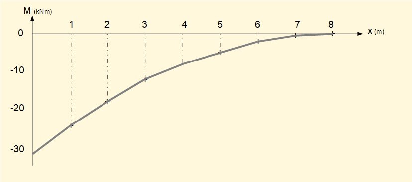
The bending moment diagram is approximate because we have joined values of M at specific points by straight lines of slope ΔM/Δx whereas M is really a quadratic function of x. We now find this function using the general relationship d2M/dx2 = -w. Consider the general model below for a beam length L with uniformly distributed load w.
From previous work above we know that the load centre of the distributed load occurs at x = L/2.
Thus the reaction moment (at point x = 0) Mre = -wL2/2
The corresponding bending moment M at x = 0 is -wL2/2 (sign convention for negative bending)
At M = L we know that M = 0 and dm/dx = 0
Now use the general relation d2M/dx2 = -w and then integrate twice to find M as a function of x. These are general integrals (no defined limits) so we must include constants of integration.
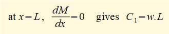
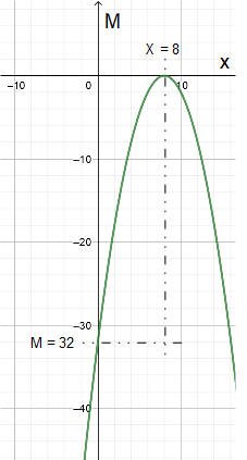
This is the general formula for the bending moment M along its length for a cantilever beam of length L and uniform distributed load w.
For the example used in this tutorial L = 8 and w = 1
The screenshot below plots this function. The part of the plot which applies is 0 ≤ x ≤ 8 and -32 ≤ M ≤ 0.
Next: Beams - bending moments and shearing forces - simply supported beam with variable distributed load
I welcome feedback at: