Many engineering structural components and machine elements take the form of a beam which bends under load. Analysis of bending and the resulting stresses and strains are the subject of several tutorials in this series.
This brief tutorial introduces the study of bending of beams by explaining basic terms and, particularly important, the sign conventions used in subsequent tutorials.
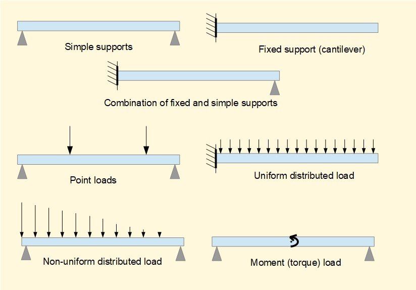
The diagrams below illustrate different types of support and loading.
We now define our conventions for positive and negative directions of loading and reaction forces, bending and shearing forces.
Positive and negative loading and reaction forces
This diagram shows the positive directions for x and y axes. Thus reaction forces R1 and R2 are positive. Loads F1 and F2 are negative.
In subsequent tutorials we will use extensively the conditions for static equilibrium ("sum of forces = 0" and "sum of moments = 0"). Be aware of the following error when writing equations for the sum of forces in the example above!
For sum of forces on the y axis = 0 it is not correct to state: R1 + R2 = - F1 - F2
It is correct to state: R1 + R2 - F1 - F2 = 0 or R1 + R2 = F1 + F2
The incorrect equation makes the mistake of a "double negative". If you are prone to this error (as I am) it helps to put all terms and their signs initially on the LHS.
Positive and negative bending
This diagram shows definitions of +ve and -ve bending.
We interpret bending as the consequence of bending moments generated by loading.
To visualise this consider an element of a beam and the bending moments that produce positive or negative bending on the element.
In subsequent tutorials we always consider sections of beams originating at the left hand end (x = 0) with the cut face at the right hand end of the section Hence the sign of the bending moment M is determined by the direction of the moment shown on the right hand face of the elements illustrated in the diagram where clockwise moments are negative and anti-clockwise moments are positive. Note that this sign convention is the reverse of the sign convention for moment loads where clockwise moments are positive and anti-clockwise moments are negative.
This difficulty regarding the sign of bending moments can be avoided by taking sections from the right hand end of the beam and reversing the +ve direction of the x axis. I find this counter-intuitive and prefer to reverse the sign of bending moments M.
Positive and negative shearing forces
Vertical loads and resultant reaction forces generate vertical shearing forces in a beam. This diagram shows definitions of positive and negative shear.
To viualise the shearing action consider an element of a beam and the shearing forces that produce positive or negative shear on the element.
In subsequent tutorials we always consider sections of beams originating at the left hand end (x = 0) with the cut face at the right hand end of the section Hence the sign of the shearing force V is determined by the direction of the force shown on the right hand face of the elements illustrated in the diagram. Note that the sign of the shearing force on the right hand hand side of an element referred to the direction of the Y axis is negative for positive shear and positive for negative shear.
This difficulty regarding the sign of shearing forces can be avoided by reversing the sign convention for vertical forces. Again,I find this counter-intuitive and prefer to reverse the sign of V.
The sign conventions for bending moment M and shearing force V for positive and negative bending and shear as defined above are universally adopted and must not be changed.
Next: Beams - bending moments and shearing forces - simply supported beam with point loads
I welcome feedback at: