Previous tutorials explain the basic concepts of stress and strain and how to find bending moments and shearing forces in beams. We now consider internal stresses generated during bending. This tutorial considers normal bending stresses σ, i.e. normal to cross-sectional faces. The next tutorial considers shear bending stresses τ, parallel to cross-sectional faces.
The model we construct is based on the following assumptions:
- pure bending (no shear forces, torsion or axial loads)
- linear-elastic behaviour under load
- the beam has constant cross-section throughout its length
- dimensions of the beam eliminate likelihood of failure modes other than bending
- cross-sections of the beam remain plane during bending
- an axis of symmetry in the plane of bending
Firstly we establish the co-ordinate system which defines positive and negative values for displacements.
This is the same x and y co-ordinate system we used for analysis of beam loading with an added z axis. Bending occurs about the z axis (the axis of bending) and the x-y plane is called the plane of bending.
Now consider how a section of a beam deforms in bending. The deformation is greatly exaggerated for the purpose of illustration.
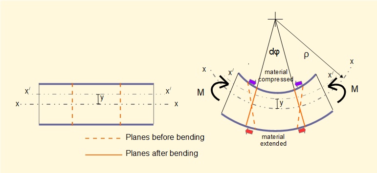
The diagram shows a section of a beam, symmetrical about the y axis. When bending moments M are applied parallel y-z planes are forced to new positions indicated by subtended angle dφ such that material in the upper section of the beam is compressed (negative strain) and material in the lower section is extended (positive strain).
The diagram shows that the x-z plane marked x-x experiences no strain during bending. This plane is called the neutral surface with radius of curvature ρ under bending conditions. An x axis on this plane determines the origin of the y and z axes in the co-ordinate system and is called the neutral axis. An arbitrary axis x/ - x/ is shown displaced +y from the neutral axis.

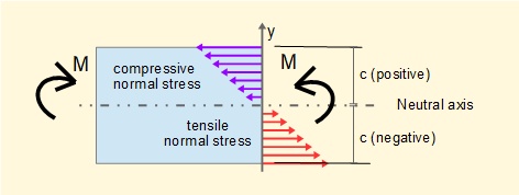
This relation indicates that σ is directly proportional to the displacement on the y axis with compressive stress for positive values of y and tensile stress for negative values of y as shown below. Maximum values of σ occur at maximum y (positive and negative) which are normally designated c. Negative values of c do not necessarily equal positive values but depend on the position of the neutral axis.
Now consider the equilibrium condition at a cross-section of the beam in bending.
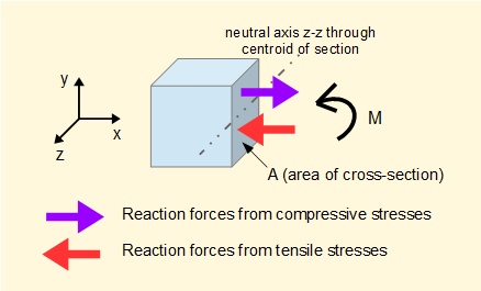
For equilibrium at this section the bending moment M must be equal and opposite to the moment generated by the reaction forces associated with the bending stresses which using the expression above for σ gives:

(for convenience it is normal in this context to omit the subscript z from I)
The first relation is important in the study of deflections of beams (see the tutorial on this subject). The latter is an important relation used to determine stresses in loaded beams.
Second moments of area I can be derived from first principles (see example below). Formulae for I for commonly used structural sections are found in standard texts. Units of I are m4.
c represents maximum +ve and -ve values of y. In our example above +ve and -ve values of c are of equal magnitude, but this is not the case when a profile is unsymmetrical about the z axis, for example a T section beam.
Clearly, in order to minimise the weight of load-supporting beams mass should be concentrated at the periphery where longitudinal bending stresses are greatest. Hence the extensive use in structural engineering of sections with I and channel profiles or hollow sections.
Derivation of second moment of area (Iz) for a rectangular cross-section
Because second moments of area I for standard structural sections are easily referenced you can, if inclined, skip this part of the tutorial. However, it is useful to know how the second moment of area is derived. We will use a rectangular section in the y-z plane for the example since the mathematical functions and limits of integration are straightforward.
The diagram of the cross section below shows an element (dA = b.dy) which facilitates the integration.
We start by considering the first moment of area Qz about the z-z axis which is:
We will not develop the integration but it is easily shown that this definite integral = 0. In fact for all plane sections the first moments of area about any centroidal axis are zero. This explains why, for bending, the neutral axis z-z is always the centroidal axis.
Iz for complex sectional profiles is typically obtained by dividing the profile into individual rectangular sections, finding Iz about the centroidal axis of each section and then using the parallel axis theorem to calculate Iz about the centroidal axis of the composite section.
Next: Shear bending stresses in beams
I welcome feedback at: