Tutorials in the section mechanics of machines have so far focused on the slider and crank mechanism which has a a very important place in mechanical engineering. In fact the slider and crank is a very specific application of a more general category of mechanism known as the four bar mechanism.
In this, the first of two tutorials, we illustrate the basic configurations of a four bar mechanism. We then demonstrate two methods of analysing the displacement of the output element of the version known as the crank rocker. In the second tutorial we construct velocity and acceleration diagrams for this mechanism and consider the slider and crank mechanism, the subject of several previous tutorials, in the context of a four bar mechanism.
Basic configurations
Below we illustrate four basic configurations of a four bar mechanism. All comprise four bars (called links) connected by four revolute joints, i.e. cylindrical joints with one degree of freedom.
One link provides an input in the form of complete or partial rotation. We call this link the crank. Another link provides the output motion. We call this link the follower or the rocker if it is only capable of partial rotation. The link between the crank and follower is called the coupler. The fourth link known as ground is a notional fixed bar providing the link between the crank and follower.Movements of four bar mechanisms with revolute joints are governed by the relative lengths of the links according to what is known as Grashof's Law. In its basic form this states that continuous rotational motion of at least one link connected to a fixed link in a four bar chain is possible only if the sum of the lengths of the shortest and longest links is less than or equal to the sum of the lengths of the remaining two links. Additional criteria under Grashof's Law for specific configurations are stated below.
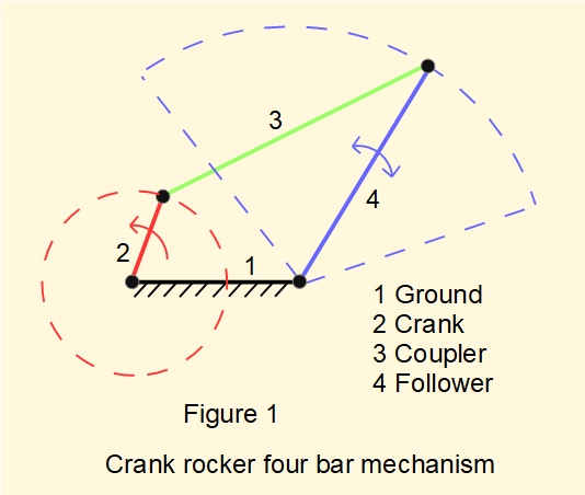
Figure 1 illustrates the crank rocker configuration where Grashof's basic criterion applies to the link lengths. The crank is capable of continuous rotation resulting in reciprocating motion of the follower, often called the rocker lever. This configuration also requires either of the two links adjacent to the shortest link to be fixed.

Figure 2 illustrates the double crank configuration where Grashof's basic criterion applies to the link lengths. Additionally, the shortest link must be fixed. Crank and follower are both capable of full rotation. This configuration is often called a drag link where the required input and output rotations are less than 360°.
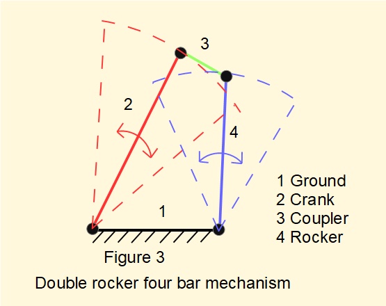
Figure 3 illustrates the double rocker configuration where the crank and rocker are restricted to reciprocating motion within defined limits. This configuration exists for two conditions: (i) where Grashof's basic criterion applies* and the coupler is the shortest link; (ii) where Grashof's basic criterion does not apply.
*note: (i) meeting Grashof's basic criterion for link lengths does not necessarily ensure that complete rotation of the input crank is possible; (ii) in this configuration complete rotation of the coupler is possible.
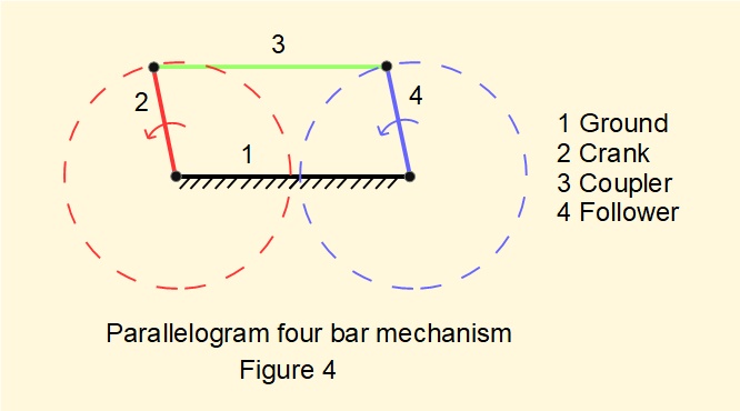
Figure 4 illustrates the parallelogram configuration. The sum of the shortest and longest links equals the sum of the remaining two links; hence from Grashof's Law continuous rotation in the form of a double crank can occur. This mechanism is very recognisable from the coupling rods that link driving wheels of railway locomotives
Kinematic analysis of a four bar mechanism
Computer software has transformed kinematic design and analysis of mechanisms for practising engineers away from traditional graphical methods and laborious calculations. However for the student it is instructive to consider displacement of the follower element using first principles. We will do this for the crank rocker configuration of a four bar mechanism.

Figure 5 above shows a crank rocker four bar mechanism where L1 is the fixed link, L2 the crank input, L3 the coupler and L4 the rocker lever output. If we define the position of the input crank as angle θ12 the position of the rocker is determined by angles θ13 and θ14. Our task is to find expressions for unknown angles θ13 and θ14 in terms of known angle θ12 and known link lengths L1, L2, L3 and L4. We can can then express point C or any other point on rocker L4 in terms of x and y co-ordinates. This process is called position analysis.
We consider two approaches to position analysis:
- Derivation using geometry
- Derivation using vector loop equations
Derivation of position using geometry
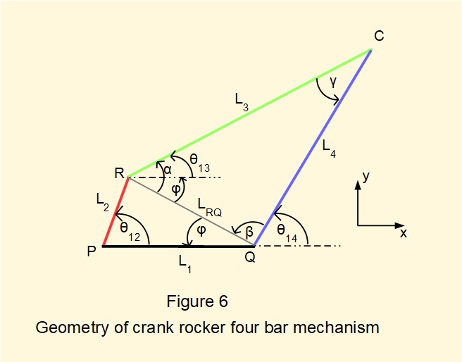
Figure 6 shows the mechanism of Figure 5 with positions of joints designated P, R, C, Q and additional line LRQ. Angles α, β, γ, and φ are defined as shown. The strategy is to develop expressions progressively for all angles using the cosine and sine laws.
Firstly find an expression for angle φ containing known parameters.
By law of cosines for triangle RPQ:
LRQ2 = L12 + L22 - 2.L1.L2.cosθ12
gives: LRQ = √[L12 + L22 - 2.L1.L2.cosθ12]
By law of sines:
sinφ/L2 = sinθ12/LRQ
gives: φ = sin-1[L2.sinθ12/LRQ]
Now find an expression for angle α containing known parameters.
By law of cosines for triangle CRQ:
L42 = LRQ2 + L32 - 2.LRQ.L3.cosα
gives cosα = [LRQ2 + L32 - L42]/2.LRQ.L3
gives α = cos-1[{LRQ2 + L32 - L42}/2.LRQ.L3]
Now find an expression for angle β containing known parameters.
By law of sines:
sinβ/L3 = sinα/L4
gives: β = sin-1[L3.sinα/L4]
From Figure 6:
θ13 = α - φ
θ14 = π - [β + φ]
γ = π - [α + β]
We now have sufficient parameters to determine positions of the rocker and coupler in terms of angles θ13 and θ14 with respect to crank angle θ12.
And finally, designating the origin for co-ordinates at joint R, co-ordinates xc and yc of point C are given by:
xc = L1 + L4.cosθ14
yc = L4.sinθ14
Alternative configuration of the mechanism
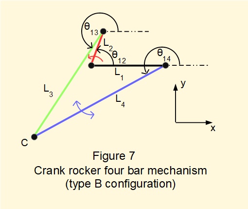
Note that the configuration of the crank rocker mechanism with link dimensions shown in Figures 5 and 6 is not unique. Consider the configuration with links of identical dimensions shown in Figure 7 below for the same crank angle θ12. In this case the coupler/rocker joint C lies below the horizontal axis of the fixed link. The expressions for position analysis developed above are equally valid for both configurations.
We will call the configuration shown in Figures 5 and 6 type A and the configuration shown in Figure 7 type B.
*Types A and B are sometimes called respectively "open" and "cross" configurations.
Computing and plotting position of the rocker
The above geometrical analysis provides an algorithm for computing the position of point C at the rocker/coupler joint. For an example we use a crank rocker mechanism as shown in Figure 8 below with crank angle θ12 = 120° (type A) and the following link lengths in arbitrary units:L1 = 2, L2 = 1, L3 = 3.5, L4 = 4

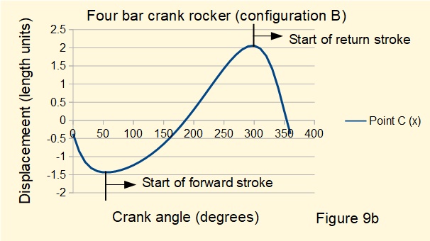
Figures 9a and 9b below show displacement of point C on the X co-ordinate for one complete revolution of the crank rotating in a counter-clockwise direction respectively for configurations A and B.
It is clearly seen that configuration A provides a fast forward and slow return stroke of the rocker. Configuration B has the opposite characteristic. It is also seen that these characteristics reverse if the crank rotates in the opposite direction. Note the similarity with complementary configurations of offset slider and crank mechanisms outlined in a previous tutorial.

The animation below illustrates the motion of both configurations with counter-clockwise rotation of the crank.
Derivation of position using vector loop equations
The geometrical analysis provided an algorithm allowing us to compute angles θ13 and θ14 for given crank angles θ12 but does not provide equations directly expressing angles θ13 and θ14 in terms of known angle θ12. This can be done using the method of vector loop equations.
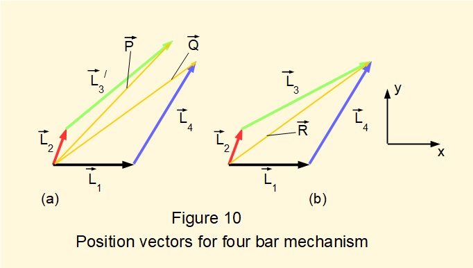
When a series of links is joined to form a mechanism where the motion is constrained, the position vectors* of the links form a vector loop. The concept is illustrated in Figure 10 above. In view (a) bars #3 and #4 are not linked and the arrangement is not constrained. Vector P = L2 + L3/ and vector Q = L1 + L4. Clearly P ≠ Q .
*In this context the origin of each position vector is the preceding joint, not a common origin.
In view (b) links #3 and #4 are joined and the arrangement is constrained. Vector R = L2 + L3 = L1 + L4. The resulting vector loop equation is defined as:
L2 + L3 = L1 + L4
The vector loop equation is often stated in the form:
L2 + L3 - L1 - L4 = 0

We now develop the vector loop equation for the four bar mechanism. Refer to Figure 11 above showing unit vectors i and j.
The vector loop equation is:
L2 + L3 = L1 + L4 where:
L1 = L1cos(0°).i + L1sin(0°).j = L1.i + 0.j
L2 = L2cos(θ12).i + L2sin(θ12).j
L3 = L3cos(θ13).i + L3sin(θ13).j
L4 = L4cos(θ14).i + L4sin(θ14).j
Taking i and j components separately in the loop equation above gives:
[L2cos(θ12) + L3cos(θ13)].i = [L1 + L4cos(θ14)].i
[L2sin(θ12) + L3sin(θ13)].j = [0 + L4sin(θ14)].j
giving scalar equations:
[L2cos(θ12) + L3cos(θ13)] = [L1 + L4cos(θ14)] ......... (1)
[L2sin(θ12) + L3sin(θ13)] = [0 + L4sin(θ14)] .......... (2)
Designating crank angle θ12 a known angle, we need to solve for two unknowns, θ13 and θ14. We choose to solve for θ14 first and will eliminate θ13 from equations (1) and (2).
Rearrange equations (1) and (2) as follows:
L3cos(θ13) = [-L2cos(θ12) + L4cos(θ14) + L1 ] ......... (3)
L3sin(θ13) = [-L2sin(θ12) + L4sin(θ14)] .......... (4)
Now square both sides of equations (3) and (4) giving:
L32cos2(θ13) = [-L2cos(θ12) + L4cos(θ14) + L1 ]2 ......... (5)
L32sin2(θ13) = [-L2sin(θ12) + L4sin(θ14)]2 .......... (6)
Adding equations (5) and (6) gives:
L32[cos2(θ13) + sin2(θ13)] = [-L2cos(θ12) + L4cos(θ14) + L1]2 + [-L2sin(θ12) + L4sin(θ14)]2 ......... (7)
as [cos2(θ13) + sin2(θ13)] = 1 equation (7) becomes:
L32 = [-L2cos(θ12) + L4cos(θ14) + L1]2 + [-L2sin(θ12) + L4sin(θ14)]2 ......... (8)
Expanding the RHS of equation (8) gives:
\(\normalsize {L_3}^2 = ( L_2. cos\theta_{12})^2 + (L_4.cos\theta_{14})^2 + L_1^2 - (2.L_2.cos\theta_{12})(L_4.cos\theta_{14}) - 2.(L_1.L_2.cos\theta_{12})+ 2.(L_1.L_4.cos\theta_{14}) + (L_2.sin\theta_{12})^2 + (L_4.sin\theta_{14})^2 - 2.(L_2.sin\theta_{12}.L_4.sin\theta_{14}) \: ......... (9) \)
Noting that: \(\normalsize ( L_2. cos\theta_{12})^2 + (L_2.sin\theta_{12})^2 = {L_2}^2 \newline and \: \: (L_4.cos\theta_{14})^2 + (L_4.sin\theta_{14})^2 = {L_4}^2 \) rearranging terms in equation (9) gives:
\(\normalsize {L_1}^2 + {L_4}^2 + {L_2}^2 - {L_3}^2 - 2.{L_1}.{L_2}.cos\theta_{12} + 2.{L_1}.{L_4}.cos\theta_{14} - 2.{L_2}.{L_4}(sin\theta_{12}.sin\theta_{14} + cos\theta_{12}.cos\theta_{14}) = 0 \:......... (10) \)
Rearranging terms in equation (10) and dividing both sides by (2.L2.L4) gives:
\(\Large \frac {{L_1}^2 + {L_4}^2 + {L_2}^2 - {L_3}^2}{2.L_2.L_4} - \frac {{L_1}.cos\theta_{12}}{{L_4}} + \frac{{L_1}.cos\theta_{14}}{{L_2}} \)
\(\normalsize = (sin\theta_{12}.sin\theta_{14} + cos\theta_{12}.cos\theta_{14}) \:......... (11) \)
In equation (11) define the following constant terms:
\(\normalsize K_1 = \Large \frac {L_1}{L_2} \: \: \: \normalsize K_2 = \Large \frac {L_1}{L_4} \: \: \: \normalsize K_3 = \Large \frac {{L_1}^2 + {L_4}^2 + {L_2}^2 - {L_3}^2}{2.L_2.L_4} \)
and use the identity: \(\normalsize (sin\theta_{12}.sin\theta_{14} + cos\theta_{12}.cos\theta_{14}) = cos(\theta_{12} - \theta_{14}) \) to give:
\(\normalsize \pmb {K_1.cos\theta_{14} - K_2.cos\theta_{12} + K_3 = cos(\theta_{12} - \theta_{14})} \:.........(12) \)
Equation (12) is called Freudenstein's equation
(Note we can derive a similar form of this equation containing cosθ12 and cosθ13 by eliminating θ14 from equations (1) and (2) above.)
Now we must solve Freudenstein's equation for θ14. One method is as follows.
Substitute the following "half angle" identities into equation (12).
\(\normalsize sin\theta_{14} = \normalsize \cfrac {2.tan (\cfrac {\theta_{14}}{2})}{1 + tan^2(\cfrac{\theta_{14}}{2})} \: \: \: \: \: \: \: \normalsize cos\theta_{14} = \normalsize \cfrac {1 - tan^2(\cfrac{\theta_{14}}{2})}{1 + tan^2(\cfrac{\theta_{14}}{2})} \)
then use the reverse identity \(\normalsize cos(\theta_{12} - \theta_{14}) = (sin\theta_{12}.sin\theta_{14} + cos\theta_{12}.cos\theta_{14}) \)
and let \(\normalsize tan (\cfrac {\theta_{14}}{2}) = P \) to give:
\(\normalsize \cfrac {K_1 - K_1.P^2 -2.P.sin\theta_{12} - cos\theta_{12}.(1 - P^2)}{(1 +P^2)} - K_2.cos\theta_{12} + K_3 = 0 \)
multiply both sides by (1 + P2) to give:
\(\normalsize K_1 - K_1.P^2 - 2.P.sin\theta_{12} - cos\theta_{12} + cos\theta_{12}.P^2 - K_2.cos\theta_{12} - K_2.cos\theta_{12}.P^2 +K_3 + K_3.P^2 = 0 \)
and express this equation as a quadratic in P giving:
\(\normalsize [cos\theta_{12} - K_1 - K_2.cos\theta_{12} + K_3].P^2 - [2.sin\theta_{12}].P + [K_1 - (K_2 + 1).cos\theta_{12} + K_3] \newline = 0 \:..........(13) \)
Now solve equation (13) for P using the quadratic formula for aP2 + bP + c = 0 where:
\(\normalsize a = cos\theta_{12} - K_1 - K_2.cos\theta_{12} + K_3\)
\(\ b = -2.sin\theta_{12} \)
\(\ c = K_1 - K_2.cos\theta_{12} - cos\theta_{12} + k_3 \)
Giving two solutions \(\ P = tan (\cfrac {\theta_{14}}{2}) = \cfrac {-b \pm \sqrt(b^2 -4ac)}{2a} \:.........(14) \)
from which \(\ \theta_{14} = 2.tan^{-1} (\cfrac {\theta_{14}}{2}) \)
Figure 12 below plots the X co-ordinate of point C against crank angle θ12 for the four bar mechanism illustrated in Figure 8 and computed using the solution:
\(\ tan (\cfrac {\theta_{14}}{2}) = \cfrac {-b \pmb{+} \sqrt(b^2 -4ac)}{2a} \)
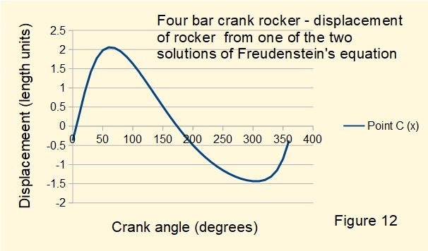
The plot replicates Figure 9a for the type A configuration with slow return characteristic derived from geometrical analysis. Correspondingly, plotting the X co-ordinate of point C against crank angle θ12 using the alternative solution:
\(\ tan (\cfrac {\theta_{14}}{2}) = \cfrac {-b \pmb{-} \sqrt(b^2 -4ac)}{2a} \)
replicates the displacement of the type B configuration with quick return characteristic.
In the next tutorial we construct velocity and acceleration diagrams for this four bar mechanism and consider the slider and crank mechanism from previous tutorials in the context of a four bar mechanism.
Next: Four bar mechanisms - 2
I welcome feedback at: