In this, the second of two tutorials on the subject of four bar mechanisms, we construct velocity and acceleration diagrams for the crank rocker mechanism considered in the previous tutorial and examine the slider crank mechanism in the context of a four bar mechanism.
Principles of velocity and acceleration diagrams
Velocity and acceleration diagrams are drawn to scale beginning with known values. Unknown values are then measured directly from the completed diagrams. It is also possible to obtain unknown values from the geometry of the diagrams.
A key point when constructing velocity and acceleration diagrams is the distinction between absolute and relative quantities. Consider the velocity diagrams in Figure 1 below which represent velocities of two pin joints in a mechanism designated a and b. Arrows va and vb represent direction and magnitude of the absolute velocities of points a and b respectively relative to point o which indicates a "ground point" in a common frame of reference.
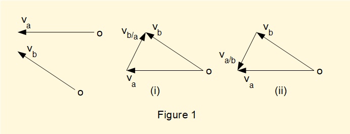
To create the velocity diagrams, va and vb are connected at their common reference point o and the diagram closed by a third arrow. In (i) the arrow direction represents the relative velocity vb/a meaning the velocity of point b relative to point a. In (ii) the arrow va/b represents the velocity of point a relative to point b.
Acceleration diagrams are constructed in a similar way to velocity diagrams bearing in mind that directions of velocity and acceleration for a point are not necessarily the same. Acceleration diagrams must also take into account that rotational motion of any point always has a radial component of acceleration directed towards the centre of rotation and a tangential component of acceleration when the point is subject to angular acceleration. The diagram below shows an acceleration diagram for the crank pin A of a rotating crank arm.
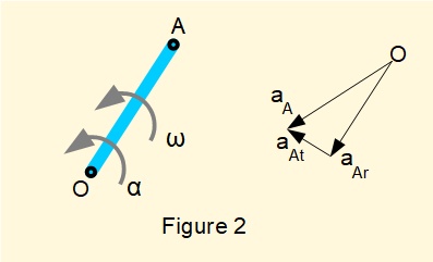
In this diagram point A rotates about point O with angular velocity ω and angular acceleration α. The diagram represents a snapshot for a specific crank angle.
- aAr is the radial (centripetal) acceleration of point A relative to point O with direction from A towards O resulting from angular velocity ω.
- aAt is the tangential acceleration of point A relative to point O resulting from angular acceleration α.
- aA is the resultant acceleration of point A relative to point O.
Be aware that point O has two slightly different interpretations in the above depending on context. In one respect point O is the centre of rotation of the crank arm AO. In a more general context it represents a ground frame of reference.
Note that arrows representing velocity and acceleration in the above diagrams are not necessarily connected as vectors in the sense that conventional representation of vector addition and subtraction does not always apply. For this reason quantities are not denoted in conventional vector form. This point is explained diagrammatically in a previous tutorial.
Velocity diagram for four bar crank rocker mechanism
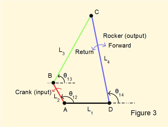
Figure 3 below shows the configuration of the four bar mechanism we used in the previous tutorial illustrated with crank angle θ12 = 120°. Note the four revolute joints are designated A, B, C and D.
Link lengths are (using metres as a unit of length for convenience):
L1 = 2 m, L2 = 1 m, L3 = 3.5 m, L4 = 4 m
The angular velocity of crank arm L2 is designated ωAB. For this example ωAB = 2π radians/s.
We now construct a velocity diagram for the crank mechanism for this crank angle.
The diagram has the following components:
- velocity of point B relative to point A (ground) designated vB/A
- velocity of point C relative to point B designated vC/B
- velocity of point C relative to point D (ground) designated vC/D which is also the velocity of point C relative to point A as point A is also a ground point. Thus we refer to this velocity as vC/A
We know the following:
- The line of action of vB/A is perpendicular to the crank arm L2. Its magnitude is
ωAB.L2 = (2π).(1) = 2π. The crank arm rotates in a counter-clockwise direction which determines the direction of vB/A - Assuming the coupler is rigid the motion of point C relative to point B must be purely rotational. Thus the line of action of vC/B is perpendicular to BC. Its magnitude is ωBC.L3.
- The line of action of vC/A is perpendicular to the follower. Its magnitude is ωCD.L4
Note at this stage ωBC and ωCD are unknown.
Figure 4 below shows the lines of action of these velocities.
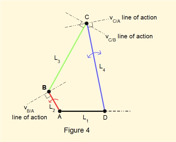
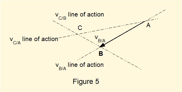
We now construct the velocity diagram. Firstly, calculate the magnitude of vB/A and draw the arrow to scale along the line of action. The head of the arrow represents point B relative to ground point A at the tail. Now draw the line of action of vC/B through point B and the line of action of vC/A through point A. The point of intersection of these two lines represents point C and determines the magnitude and direction of vC/B and vC/A.
Figure 5 below illustrates this construction.
The completed velocity diagram is shown below. Note that magnitude and direction of vC/B and vC/A are both determined by this construction, the head of the arrow representing the velocity at that point relative to the point at the tail.
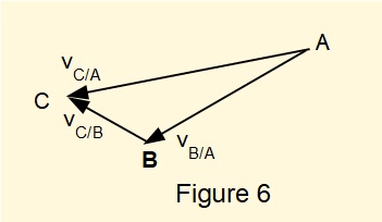
Values scaled from well drawn velocity diagrams are sufficiently accurate for practical purposes. Alternatively, velocities can be calculated directly from the diagram.
Referring to Figure 3, angles computed from the algorithm for position analysis for crank angle
θ12 = 120° (see the previous tutorial) are:
θ13 = 60.8°
θ14 = 101.4°
From geometry, angles in triangle ABC in Figure 6 are resolved as follows:
angle A = 18.6°
angle B = 120.8°
angle C = 40.6°
Given the magnitude of velocity vector vB/A = 2π it follows from the law of sines that:
\(\normalsize \cfrac{BC}{sinA}=\cfrac{AC}{sinB}=\cfrac{AB}{sinC} \) to give \( \cfrac{AB}{sinC}=\cfrac{2.\pi}{sin40.6\degree}=9.65 \)
Giving BC = magnitude of vC/B = 3.01 m/s and AC = magnitude of vC/A = 8.29 m/s
The magnitude of the corresponding angular velocities for the coupler (ω13) and rocker (ω14) are thus:
ω13 = vC/B/3.5 = 0.86 radians/s
ω14 = vC/A/4.0 = 2.07 radians/s
Velocity plots
Figure 7 below plots velocity vC/A at end point C of the rocker for a complete crank cycle derived from velocity diagrams constructed at intervals of 10 degrees.
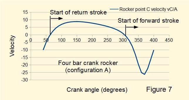
The diagram clearly shows the fast forward/slow return characteristic of this configuration. Figure 8 below shows the corresponding plot for angular velocity of the rocker ω14. Note the convention of positive counter-clockwise rotation (return stroke) and negative clockwise rotation (forward stroke) replicated in the velocity plot.
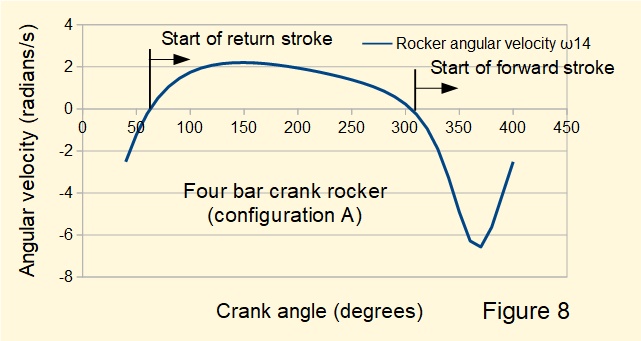
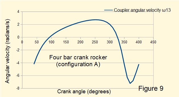
Figure 9 below plots the angular velocity of the coupler ω13 over one crank cycle. Note that changes of direction of rotation of the coupler do not occur at transitions between forward and return strokes of the rocker.
Derivation of angular velocity by differentiation
There is a very elegant method for determining angular velocities ω13 and ω14 by differentiating the vector loop equation for position analysis from the previous tutorial expressed in exponential complex form, namely:
\(\large\ L_2 + L_3 = L_1 + L_4 \) expressed as:
\(\large\ {L_2}.e^{i. \theta _{12}} + {L_3}.e^{i. \theta _{13}} = L_1 + {L_4}.e^{i. \theta _{14}} \)
differentiating θ12, θ13 and θ14 with respect to time gives:
\(\large\ i.{L_2} .\omega_{12}.e^{i. \theta _{12}} + i.{L_3}.\omega_{13}.e^{i. \theta _{13}} = i.L_4.\omega_{14}.e^{i. \theta _{14}} \)
Eliminating i and rearranging gives:
\(\large\ {L_3}.\omega_{13}.e^{i. \theta _{13}} - L_4.\omega_{14}.e^{i. \theta _{14}} = -{L_2} .\omega_{12}.e^{i. \theta _{12}} ......... (1) \)
To solve for θ13 in terms of θ12 multiply equation (1) by e-i.θ14 giving:
\(\large\ {L_3}.\omega_{13}.e^{i. (\theta _{13}-\theta_{14})} - L_4.\omega_{14} = -{L_2} .\omega_{12}.e^{i. (\theta _{12}-\theta_{14})} \)
Applying Euler's formula: \(\large\ e^{i\theta} = cos \theta +i.sin \theta \) gives:
\(\large\ L_3.\omega_{13}[cos(\theta_{13}-\theta_{14}) + i.sin(\theta_{13}-\theta_{14})] - L_4.\omega_{14} = -L_2.\omega_{12}[cos(\theta_{12}-\theta_{14}) + i.sin(\theta_{12}-\theta_{14})] \)
Expressing only the imaginary terms gives the equation:
\(\large\ L_3.\omega_{13}.sin(\theta_{13}-\theta_{14}) = -L_2.\omega_{12}.sin(\theta_{12}-\theta_{14}) \)
Giving:
\(\large\ \omega_{13} = \omega_{12}. \cfrac {-L_2.sin(\theta_{12}-\theta_{14})}{L_3.sin(\theta_{13}-\theta_{14})}\)
which can be expressed as: \(\large\ \omega_{13} = \omega_{12}. \cfrac {L_2.sin(\theta_{12}-\theta_{14})}{L_3.sin(\theta_{14}-\theta_{13})} ........ (2)\)
Correspondingly, to solve for θ14 in terms of θ12 multiply equation (1) above by e-i.θ13 to give the following expression for θ14:
\(\large\ \omega_{14} = \omega_{12}. \cfrac {L_2.sin(\theta_{12}-\theta_{13})}{L_3.sin(\theta_{14}-\theta_{13})} ........ (3)\)
Equations (2) and (3) represent precisely the geometry of the velocity diagrams illustrated previously.
Acceleration diagram for four bar crank rocker mechanism
Our example of an acceleration diagram for the four bar crank rocker is based on a crank angle (θ12) of 350°. The reason can be seen from Figures 8 and 9 showing angular velocities ω13 and ω14 are relatively small at a crank angle of 120°. Thus the radial components of acceleration are also relatively small, being proportional to ω2. Consequently the acceleration diagram is not ideal for illustrating the method of construction.
Figure 10 below shows lines of action and directions, where known, for radial (subscript r) and tangential (subscript t) components of acceleration for bars L2, L3 and L4 at a crank angle of 350°. Note that we designate point A as the ground reference point for links L2 and L4
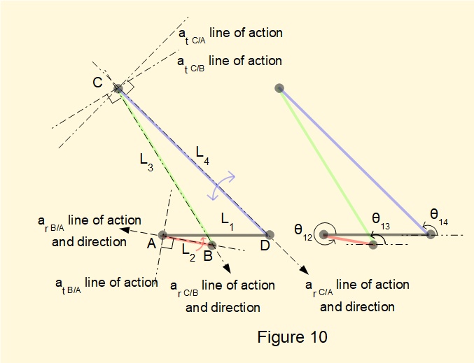
Angles θ13 = 121.7° and θ14 = 135.4° (obtained by position analysis from the previous tutorial)
From construction of the velocity diagram above we know:
- Link lengths L1 = 2 m, L2 = 1 m, L3 = 3.5 m, L4 = 4 m
- angular velocity ω12 of crank L2 = 2.π radians/s (constant).
- angular velocities ω13 of link L3 and ω14 of link L4 at crank angle 350° from calculation are:
ω13 = 4.26 radians/s ω14 = 4.92 radians/s
Thus radial components of acceleration ar B/A, ar C/B, ar C/A are as follows:
ar B/A = (ω12)2.L2 = 39.4 m/s2
ar C/B = (ω13)2.L3 = 63.5 m/s2
ar C/A = (ω14)2.L4 = 96.8 m/s2
Because crank L2 has constant angular velocity the tangential component of acceleration at B/A is zero.
Lines of action of tangential components of acceleration at C/B and at C/A are known. Their magnitudes will be determined from the diagram.
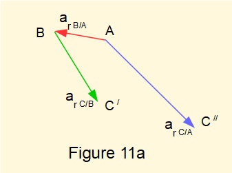
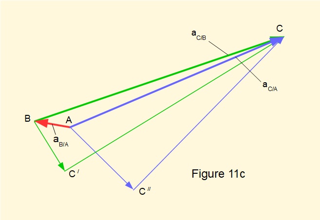
We start the acceleration diagram in Figure 11a by plotting to scale the radial components of acceleration along their lines of action with their known magnitude and direction. If necessary, refer to Figure 2 above which explains the direction and designation of points on the diagram. Points representing intermediate stages to point C are designated C/ and C//.
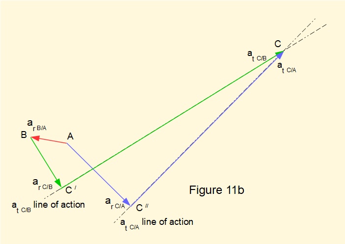
In Figure 11b we plot lines of action for tangential components at C/B and at C/A. The intersection of these lines represents point C. Thus magnitudes of at C/B and at C/A are determined by scaling lines C/C and C//C respectively.
In Figure 11c we complete the diagram by plotting and scaling lines BC and AC which represent resultant accelerations aC/B and aC/A respectively. Note that ar B/A = aB/A as there is no tangential component of acceleration.
The acceleration diagram provides the means of determining angular accelerations α13 for coupler L3 and α14 for rocker L4 using expressions:
α13 = L3.at C/B
α14 = L4.at C/A
Scaling from the acceleration diagram gives at C/B = 282.0 m/s2 and at C/A = 253.0 m/s2.
Giving: α13 = 80.0 radians/s2 and α14 = 63 radians/s2. These values can be verified to a reasonable degree by estimating rates of change of ω13 and ω14 from Figures 8 and 9 above.
The signs of α13 and α14 are deduced from the acceleration diagram using the vector* relationship:
*in this case treating the arrows in the diagram as vectors.
α = r x at
where r represents position vectors BC/ and AC//. At this position of crank angle (350°), α13 and α14 are both positive (i.e. counter-clockwise rotation), again illustrated in Figures 8 and 9, whilst angular velocities ω13 and ω14 are negative (clockwise rotation). The characteristics of ω and α for the coupler and rocker are similar to those of the connecting rod in a slider and crank mechanism illustrated in a previous tutorial.
Slider and crank as a four bar mechanism
We can consider a slider and crank mechanism as a special case of a four bar crank rocker mechanism in the following way. Consider Figure 12a below.
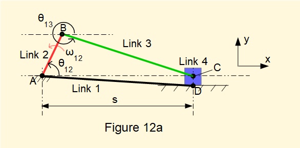
Link 2 (crank) and link 3 (coupling rod) are connected at both ends by revolute joints. Link 4 (slider) connects with the ground plane through a prismatic joint at a notional point D linked to ground point A forming link 1 of varying horizontal length s.
Now consider this arrangement of links using the vector loop method described in the previous tutorial.
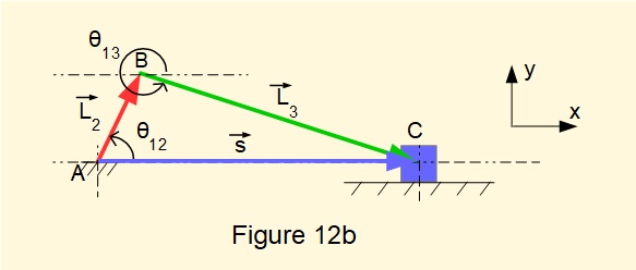
Figure 12b shows the vector loop with links 2 and 3 represented by position vectors L2 and L3, based on a notional break in the loop at joint C. We represent link 4 (the slider) as position vector s of variable magnitude in the horizontal direction from ground point A to point C, in effect "shorting out" ground link AD. This gives the following vector loop equation:
L2 + L3 = s
We can express this equation in terms of complex components where:
L2 = L2.cosθ12.i + L2.sinθ12.j
L3 = L3.cosθ13.i - L3.sinθ13.j (noting that L3.sinθ13 has direction - j)
s = s.i + 0.j
Separating i and j components gives two scalar equations with two unknowns: θ13 and s.
L2.cosθ12 + L3.cosθ13 = s ......... (1)
L2.sinθ12 - L3.sinθ13 = 0 .......... (2)
Equation (2) gives: sinθ13 = [L2/L3].sinθ12 ......... (3)
Thus we can determine angle θ13 for any given crank angle θ12 where L2 and L3 are defined. The magnitude of s can then be determined by substituting this value of θ13 into equation (1).
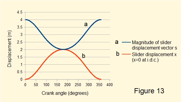
In Figure 13 below plot(a) is the magnitude of vector s, that is displacement of the slider on the horizontal axis measured from the centre of rotation of the crank, computed from the above equations for one complete crank cycle.
Plot (b) shows the same computation with the datum on the horizontal axis adjusted to the inner dead centre (i.d.c.) position of the slider. This plot is identical to that in a previous tutorial where we derived the following expression for slider displacement x:
\(\large\ x = L_2[1-cos\theta_{12} + n - \sqrt{(n)^2 - sin^2\theta_{12}}] \)
where \(\large\ n = \cfrac{L_3}{L_2} \)
Next: Return to: Content - mechanics of machines
I welcome feedback at: