In this tutorial we examine gyroscopic effects when the axis of rotation of a rotor of significant mass and angular velocity changes, as, for example, in aero engines, wind turbines and rotating machinery on ships. We conclude with a brief review of the precessional motion of a gyroscope.
The gyroscopic effect
In the following analysis the co-ordinate system and directions of vector quantities relating to rotational motion are determined by the right hand rule.
Figure 1(a) below shows a disc with moment of inertia I rotating on a central spindle with angular velocity Ω about principal axis of inertia x. In the absence of friction the disc will continue to rotate on this axis indefinitely assuming there is no irregularity in the distribution of mass within the disc.
Angular momentum of the rotating disc L = IΩ. Vectors L and Ω act along the x axis.
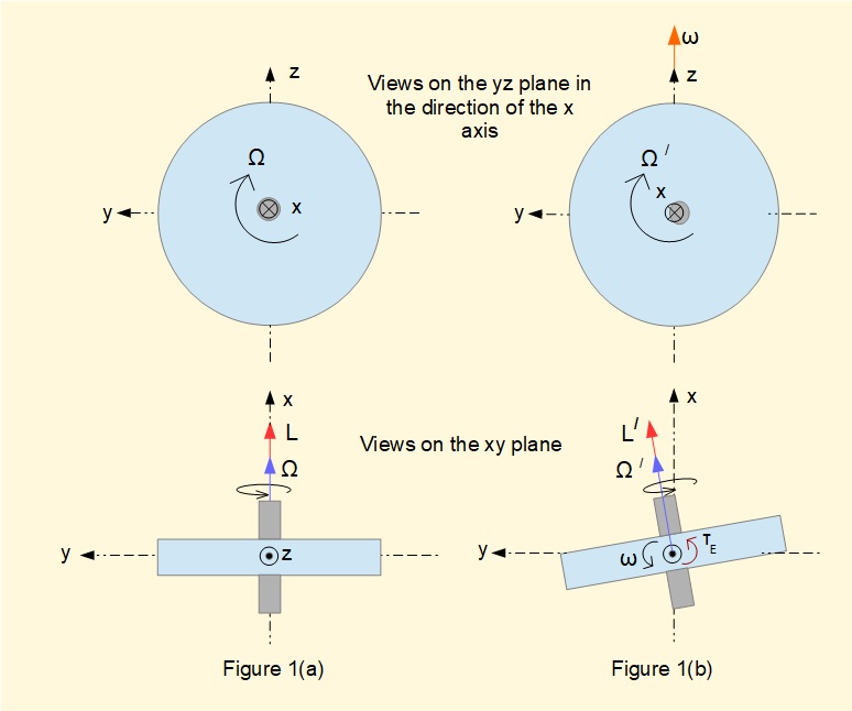
In Figure 1(b) the disc is tilted about the z axis in the xy plane with angular velocity ω by applying a torque τE from an external source. Vector ω acts along the z axis in the positive direction.
Figures 2(a), (b), (c), (d) and (e) below illustrate the effect of applying torque τE in terms of vector quantities.
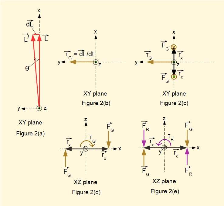
Figure 2(a) in the xy plane is a vector diagram showing the change in angular momentum dL from L to L/ effected by a change in the axis of rotation of the disc in the xy plane through a very small angle θ as in Figure 1(b). As θ is very small the direction of dL can be taken to align along the y axis.
By the laws of classical mechanics any change in angular momentum induces a torque τ which is equal to the rate of change of the angular momentum, i.e.
τ = dL/dt
Thus the direction of vector τ must be the same direction as dL which in this example is a positive direction on the y axis, as shown in Figure 2(b). We call this induced torque the gyroscopic torque, τG which produces a moment acting on the rotating disc and spindle about the y axis. In practical engineering applications the effects of gyroscopic moments are significant only where |ω| ≪ |Ω|.
Figure 2(c) shows the gyroscopic moment acting on the spindle in the xy plane in terms of forces FG applied at position vectors rx on the x axis, with the gyroscopic torque vector τG directed along the y axis in the positive direction. Position vectors rx represent the location of bearings on the spindle axis. Note that vector cross product rx x FG = τG.
Figure 2(d) also shows the gyroscopic moment but viewed on the xz plane looking along the positive direction of the y axis.
From an engineering perspective a critical aspect of the gyroscopic torque is the reactive torque τR acting in the opposite direction to τG and resulting in reaction forces FR at bearing positions, illustrated in Figure 2(e).
An expression for the gyroscopic torque
Before presenting a practical example where the gyroscopic moment has a significant effect we will derive an expression for the gyroscopic torque τG from first principles.

Figure 3(a) shows scalar quantities L, L/ and δL corresponding magnitudes of the vector quantities in Figure 2(a).
We previously noted:
- I is the moment of inertia of the disc about principal axis of inertia x
- Ω is the angular velocity of rotation of the disc about the x axis
- ω is the angular velocity of rotation of the disc about the z axis from application of external torque τE
Let the rotating disc tilt about the z axis by small angle δθ
From classical mechanics we know scalar quantities L = L/ = I.Ω
From the geometry of Figures 3(a) and 3(b): δL = L.δθ = I.Ω.δθ
Again, from classical mechanics we know that torque (τ) = rate of change of angular momentum (L)
Which we can express for the gyroscopic torque τG from the above relations as:
\(\large\ \tau_{G} = \dfrac{\delta {L}}{\delta{t}}=I.\Omega.\dfrac{\delta \theta}{\delta {t}} \)
Giving: \(\large\ \tau_{G} = I.\Omega.\omega \)
Practical application
The following example shows the effect of the gyroscopic torque induced in a propulsion unit on a ship, say a gas turbine running at 10,000 revs/min.
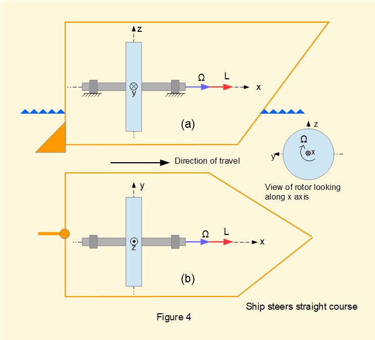
Figures 4(a) and (b) above are views (elevation and plan respectively) of a ship on a straight course. The single rotor supported by two bearings represents the combined inertia of multiple compressor and turbine rotors. Vectors show the angular velocity Ω and angular momentum L of the rotor.
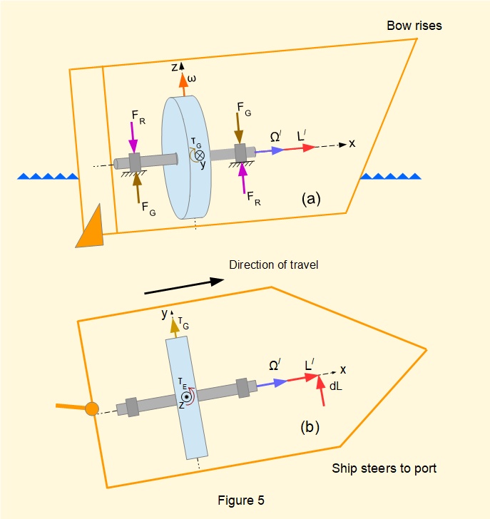
Figures 5(a) and (b) above in elevation and plan illustrate the effect of the ship steering to port.
Referring to the previous section, the ship's rudder generates torque τE which tilts the rotor assembly about the z axis (see Figure 5(b)).
τE induces gyroscopic torque τG (see Figure 5(a)).
τE produces a gyroscopic moment through forces FG applied at the rotor bearings. The corresponding reaction couple at the bearings represented by forces FR raises the bow of the ship.
Correspondingly, if the direction of rotation of the rotor or the direction of rotation of the course change are reversed the bow will dip. Motion resulting from generation of gyroscopic torque in general is called processional motion.
Other effects of gyroscopic torque induced in high speed-rotating equipment in ships and aircraft include:
- A ship pitching from bow to stern induces sideways roll.
- A yaw manoeuvre induces the nose of an aircraft to rise or fall.
- Change of pitch induces sideways roll of an aircraft.
Quantifying gyroscopic torque and bearing load
We can estimate rotor bearing reaction forces generated in a ship's propulsion unit when changing course for the following hypothetical conditions:
- Rotor speed Ω = 10,000 revs/min = 1047 rad/s
- Combined compressor and turbine rotor mass = 200 kg
- Distance between two rotor bearings = 0.4 m (equispaced either side of the rotor)
- Radius of gyration of rotor = 0.28 m
- Angular velocity ω of course change = 0.08 rad/s (represents a 45° course change in 10 seconds)
The above gives moment of inertia of the rotor I = (200) x (0,28)2 = 15.7 kgm2
Giving gyroscopic torque τG = I.Ω.ω = (15.7) x (1047) x (0.08) = 1.32 kNm
Giving the reaction force FR at each bearing = 1.32/(2 x 0.2) = 3.3 kN
In practice gas turbines have more than two bearings on the main shaft hence individual bearing loads will be lower than the above. Nevertheless this estimation indicates the high bearing loads typically generated by gyroscopic torques.
Source of gyroscopic torque (Descriptive explanation)
The gyroscopic torque induced when the axis of rotation of a rotating mass tilts is not an intuitive phenomenon. The following descriptive explanation* provides some insight. A more rigorous approach from basic principles of mechanics can be found in text books.
*the basis of this description is from Mechanics, Chapter XVII, J.P. Den Hartog, Dover 1961 edition.
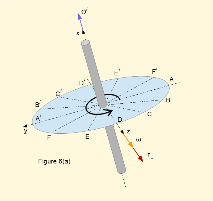
Figure 6(a) above shows a disc mounted on a spindle rotating in a positive counter-clockwise direction with original angular velocity Ω about the x axis in a right hand co-ordinate system. The disc is tilted about the z axis in a counter-clockwise positive direction by external torque τE with constant angular velocity ω. Ω/ represents the changing angular velocity vector of the disc. Six equally-spaced diametrical lines define twelve points on the circumference. These points aid the description which follows.
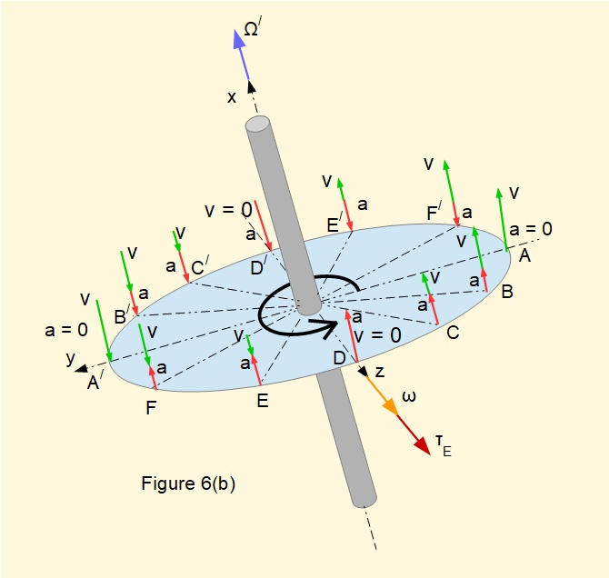
Consider the disc presented in Figure 6(b) above.
Imagine small mass elements of the disc rotating at each of the twelve positions indicated on the diagram. Each element has components of velocity v and acceleration a perpendicular to the plane of the disc attributable to rotation of the disc at constant angular velocity ω about the z axis.
We see that:
- v = 0 at points D and D/.
- v is a maximum at points A and A/.
At the other points on the circumference v is proportional to the perpendicular distance from the z axis. Velocity vectors on the left hand side of the disc are directed perpendicularly downwards, those on the right hand side are directed perpendicularly upwards
Consider accelerations a for mass elements from points D to A. Velocity at each point increases thus directions of velocity and acceleration are the same. However the rate of increase in velocity reduces, i.e. acceleration reduces. Where velocity reaches a maximum at point A, acceleration is zero.
Now consider accelerations for mass elements from points A to D/. Velocity at each point reduces thus directions of acceleration and velocity are opposed.
We can repeat this logic for sections D/ to A/ and A/ to D.
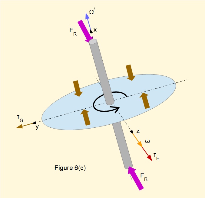
By extending this pattern of acceleration of the mass elements at the circumference of the disc to an integration over the entire disc, it follows that perpendicular accelerations must be the result of opposing forces acting on either side of the y axis, thus generating a counter-clockwise, positive gyroscopic torque τG, shown in Figure 6(c) below.
Reaction forces FR acting on the spindle oppose the gyroscopic torque τG.
Gyroscopic precession
It would be remiss in this tutorial not to finish with a short section about gyroscopic precession, which is the most widely recognised manifestation of the gyroscopic effect.
In all the above examples the induced gyroscopic torque τG is opposed by a reaction torque from bearings that secure the rotor. We now examine an arrangement where a rotor with a high rotational speed is unrestrained by a reaction torque. This is the condition in a gyroscope, which is illustrated in Figure 7 below.
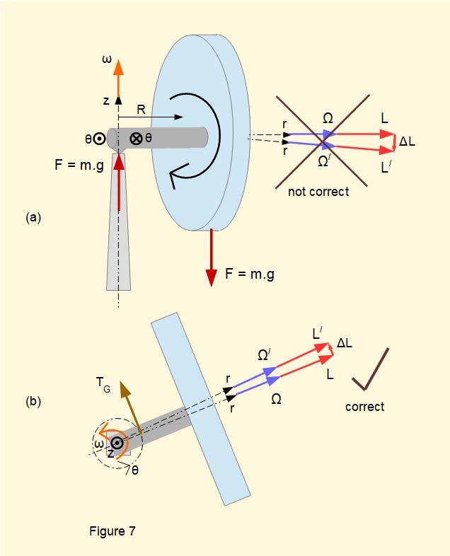
The simplest form of a gyroscope is a cylindrical rotor mounted centrally on a spindle of length R with a frictionless bearing, shown in Figure 6(a) in elevation and Figure 6(b) in plan views*. There is an external means whereby the rotor is brought to a high angular velocity Ω. The free end of the spindle is then placed on a vertical pillar on a point bearing which offers no resistance to an applied moment.
*Demonstrations often use a bicycle wheel with a free-running hub.
The rotor is set in a right hand cylindrical co-ordinate system, r, θ and z, with angular velocity Ω and angular momentum L acting along the r axis in a positive direction.
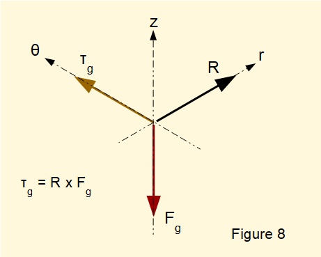
In view (a) note the the downward gravitational force Fg acting through the centre of gravity of the rotor (assume the spindle has zero mass). There is an equal and opposite reaction force at the point bearing on the support pillar. Fg acting through the centre of mass generates a torque τg with moment arm R.
At this point it is easy to make an error. Intuitively we might think τg tips the rotor downward, whereby the change in angular momentum ΔL is directed downwards on the z axis. However, as illustrated in Figure 8 below, the vector cross product τg = R X Fg establishes τg acting tangentially on the θ axis. The change in angular momentum of the rotor ΔL must also be in this direction from the relationship
τ = dL/dt.
Thus τg = the gyroscopic torque τG. As τg is always present there will be continuous change in angular momentum tangentially around the θ axis such that rotor and spindle orbit continuously on a circular path at constant angular velocity ω. The r axis maintains a horizontal plane, provided angular velocity of the rotor Ω remains high. This motion is called gyroscopic precession.
In a practical gyroscope with friction at the bearings Ω slowly reduces in magnitude. Precession continues but at a declining angle of the r axis until the gravitational force Fg pulls the rotor and spindle off the support pillar.
Next: Mechanics of machines - Contents
I welcome feedback at: