Our tutorials so far have covered bending stresses and deflections in beams acting as a single homogeneous structural member. There is another structural element in engineering which has the same function as a beam but is made from individual members jointed at each end to form a frame, commonly known as a truss.
Trusses are typically used in bridges, roofs, cranes and many other structures.
In this tutorial we determine the forces in individual members of a truss under load conditions using conditions of static equilibrium at each joint in the example below. It should be noted that this method is valid only for statically determinate structures.
Statically determinate means for a two-dimensional structure that the reaction forces resulting from loading can be determined by the three equations for static equilibrium (sum of forces on x and y axes = 0 and sum of moments about any point = 0). The formula b = (2j - 3) is the criterion for a statically determinate truss where b is the number of bars and j the number of joints. Our example below has 11 bars and 7 joints.
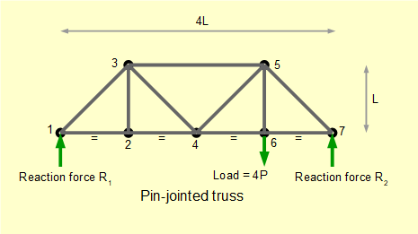
The bars of this truss are connected by hinged joints (often referred to as pin joints) which cannot transmit moment loads. All loads act along the longitudinal axes of the bars which are thus in pure tension or compression. Very small distortions in the bars arising from strains can be ignored. Even when the bars are rigidly connected, for example using bolted gusset plates, analysis shows relatively small deviations from the stresses in the members derived using hinged joints. All load and reaction forces are assumed to act at joints.
Although the basic method for resolving forces in the bars is straightforward, determining the signs of forces requires care. The method below focuses on avoiding such errors.
The basis for my example is identical to the explanatory example in Mechanics, J P Den Hartog, Dover edition, 1961. The "method of joints" solution presented by Den Hartog is essentially graphical, unlike my admittedly more laboured approach . If you prefer an elegant graphical solution consult this classic text, which I believe is still in print.
Firstly find reaction forces R1 and R2 using our sign conventions for forces and moments.
Sum of moments about pin #7 = 0
(R1)(L) - (4P)(L/4) = 0
Gives: R1 = P
Sum of forces = 0
R1 + R2 - 4P = 0 gives; R2 = 4P - P
Gives: R2 = 3P
We now resolve forces in each bar by considering free body diagrams around each pin successively from pin #1 to pin #7.
Below is the free body diagram for pin #1 which includes short stubs of each connected bar (subscripts indicate the linked joints). Note the x and y axes which define +ve and - ve directions for forces. Also note that θ = 45 deg.
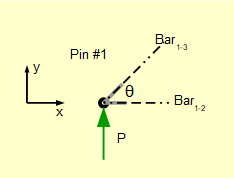
We know reaction force P. Forces F1-2 and F1-3 acting along the lines of the respective bars are unknown. We make no intuitive assumptions initially regarding the direction of horizontal and vertical components of unknown forces and use the notation ± F.
Take Σ of vertical forces = 0 (F1-2 has no vertical component)
P ± (F1-3 .Sinθ) = 0 thus as P is +ve,(F1-3. Sinθ) must be -ve
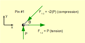
Gives (absolute value):: F1-3 = (P/ Sinθ) = √2(P)
Now consider the direction of F1-3 in the free body diagram based on the direction of its vertical component. The bar is pushing the pin and the reaction force from the pin is pushing the bar. Thus the bar is in compression. It is important to understand that -ve vertical components do not necessarily result in compressive forces as we will see when considering subsequent pins.
Take Σ of horizontal forces = 0 (noting that the horizontal component of F1-3 is -ve)
- (F1-3.Cosθ) ± F1-2 = 0 thus as F1-3.Cosθ is -ve, F1-2 must be +ve
Gives (absolute value): F1-2 = (F1-3.Cosθ) = √2(P)(Cosθ) = P
In this case the bar is pulling the pin and the reaction force from the pin is pulling the bar. Thus the bar is in tension.
The completed free body diagram for pin #1 is as follows.
If you have absorbed this method of resolving forces at a pin joint you can jump to the summing-up section at the end of this tutorial. If not, the procedure is repeated for joints #2 to #7 below.
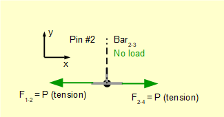
For pin #2.
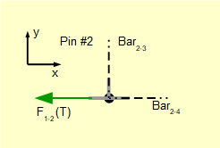
At pin #1 we showed that F1-2 puts bar1-2. in tension. This means that F1-2 exerts a pulling force on pin #2 in the -ve direction.
Take Σ of vertical forces = 0
F1-2 and F2-4 have no vertical components. Thus F2-3 = 0
Take Σ of horizontal forces = 0
-F1-2 ± F2-4 = 0 Thus F2-4 is +ve.
Gives (absolute value): F2-4 = F1-2 = P (obvious intuitively but I am stressing a "non-intuitive" approach for signs of forces)
The direction of F2-4 shows a pulling force on the pin. Thus bar2-4 is in tension. The completed free body diagram for pin #2 is as follows.
For pin #3.
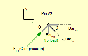
We know bar1-3 is in compression and bar2-3 has no load.
Take Σ of vertical forces = 0
(F1-3. Sinθ) ± (F3-4.Sinθ) = 0 Thus (F3-4.Sinθ) is -ve and it follows that (F3-4.Cosθ) is +ve.
Gives; (F3-4. Sinθ) = (F1-3.Sinθ)
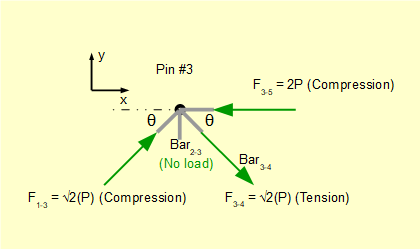
Gives a pulling tensile force (absolute value) F3-4 = F1-3 = √2(P)
Take Σ of horizontal forces = 0
(F1-3.Cosθ) + (F3-4.Cosθ) ± F3-5 = 0 Thus F3-5 is -ve.
Gives: F3-5 = (F1-3.Cosθ) + (F3-4.Cosθ) = P + P = 2P
Gives a pushing compressive force (absolute value) F3-5 = 2P
The completed free body diagram for pin #3 is as follows.
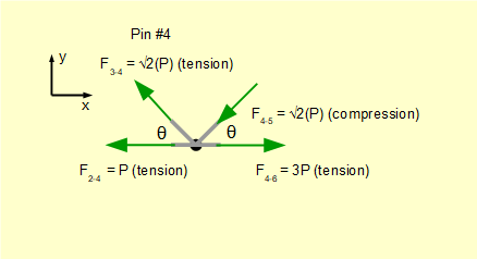
For pin #4.
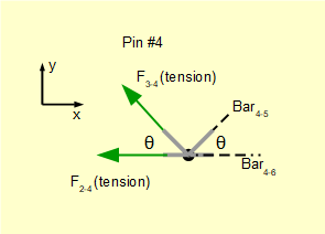
We know bar2-4 and bar3-4 are in tension.
Take Σ of vertical forces = 0
(F3-4.Sinθ) ± (F4-5.Sinθ) = 0 Thus (F4-5.Sinθ) is -ve.
Gives: (F4-5.Sinθ) = (F3-4.Sinθ)
Gives a pushing compression force (absolute value) F4-5 = F3-4 = √2(P)Take Σ of horizontal forces = 0
-(F3-4.Cosθ) - (F4-5.Cosθ) - F2-4 ± F4-6 = 0 Thus F4-6 is +ve.
Gives: F4-6= (F3-4.Cosθ) + (F4-5.Cosθ) + F2-4
Gives a pulling tensile force (absolute value) F4-6 = P + P + P = 3P
The completed free body diagram for pin #4 is as follows.
For pin #5.
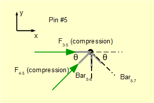
We know bar3-5 and bar4-5 are in compression. For this pin joint there are three forces with vertical components but only the vertical component of F4-5 is known. Thus first resolve horizontal forces to find F5-7.
Take Σ of horizontal forces = 0
F3-5 + (F4-5.Cosθ) ± (F5-7.Cosθ) = 0 Thus F5-7.Cosθ is -ve.
Gives: (F5-7.Cosθ) = (F4-5.Cosθ) + F3-5
Gives: F5-7 = F4-5 + F3-5 / Cosθ
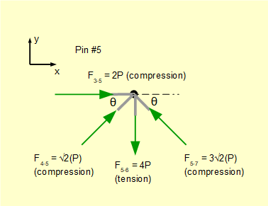
Gives a pushing compressive force (absolute value) F5-7 = √2(P) + √2(2P) = 3√2(P)
Take Σ of vertical forces = 0 (noting that (F5-7.Sinθ) is +ve)
(F4-5.Sinθ) + (F5-7.Sinθ) ± F5-6 = 0 Thus F5-6 is -ve.
Gives: F5-6 = (F4-5.Sinθ) + (F5-7.Sinθ)
Giving a pulling tensile force (absolute value) F5-6 = P + 3P = 4P
The completed free body diagram for pin #5 is as follows.
For pin #6.
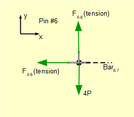
We know bar4-6 and bar5-6 are in tension. Taking Σ of vertical forces = 0 confirms that F5-6 = +4P as determined for pin #5.
Take Σ of horizontal forces = 0
-F4-6 ± F6-7 = 0 Thus F6-7 is +ve.
Gives: F6-7 = F4-6
Giving a pulling tensile force (absolute value) F6-7 = 3P
The completed free body diagram for pin #6 is as follows.
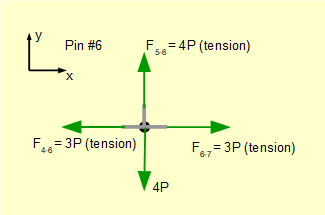
For pin #7.
Forces in the two bars linked at pin #7 have already been resolved. We can review the free body diagram to confirm that our calculations are correct. Note we could equally well have started calculations at pin #7 working back to pin #1.
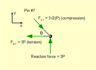
Compute Σ of vertical forces:
3P - 3√2(P)Sinθ = 3P - 3√2(P) / √2 = 0 (condition for equilibrium met)
Compute Σ of horizontal forces:
3√2(P)Cosθ - 3P = 3√2(P) / √2 = 0 (condition for equilibrium met)
Forces in the bars of the truss are shown in the following table.
| Bar | Force | Direction of force |
|---|---|---|
| 1-2 | P | tension |
| 1-3 | √2(P) | compression |
| 2-3 | 0 | |
| 2-4 | P | tension |
| 3-4 | √2(P) | tension |
| 3-5 | P | compression |
| 4-5 | √2(P) | compression |
| 4-6 | 3P | tension |
| 5-6 | 4P | tension |
| 5-7 | 3√2(P) | compression |
| 6-7 | 3P) | tension |
It is interesting to visualise in the diagram below forces acting on individual bars. Width of the line representing each bar is proportional to the force acting on the bar as are the arrows representing the applied force and reactions.
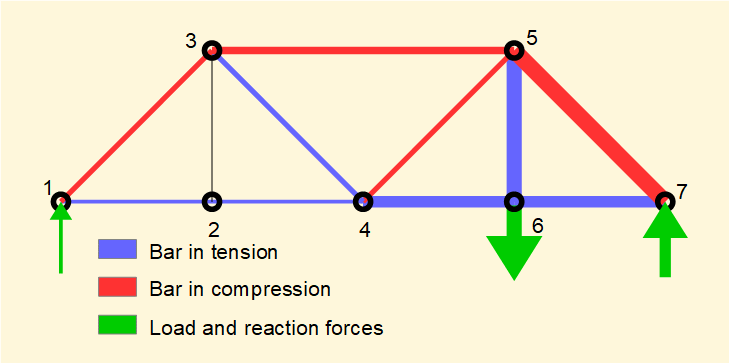
Next: Torsional stresses
I welcome feedback at: