Next: Forces in structural trusses
I welcome feedback at:
In previous tutorials we considered normal and shear bending stresses in beams under load which allows us to determine whether the beam has sufficient strength to carry the expected load.
Another consideration for design is that the deflection under load is acceptable. In this tutorial we look at methods of determining deflections of beams in bending.
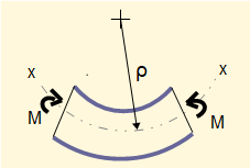
In a previous tutorial we established the relationship between bending moment M and radius of curvature ρ of the neutral axis x-x in the plane of bending as shown in this (greatly exaggerated) diagram:


E is the modulus of elasticity and I is the second moment of area about the z axis.

In bending dy/dx is small and thus the denominator of the above expression reduces to 1 and we obtain the relationship:

The diagram below shows the slope (dy/dx) and deflection (y) of the neutral axis xx in bending.

If we have an expression for bending moment M as a function of x we can obtain expressions for the slope and deflection by successive integrations.

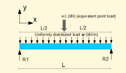
We will now derive expressions for slope (dy/dx) and deflection (y) for a simply supported beam with uniform distributed load shown below.

The first step is to derive a general expression in x for bending moment M.
Firstly find reaction forces R1 and R2
Consider Σ forces = 0 (note sign convention)
R1 + R2 - wL = 0 ------------ (i)
Consider Σ moments = 0 at position x = 0 (+ve moments are clockwise)


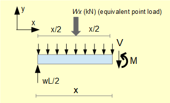
To find shearing force V and bending moment M consider a section of beam at position x shown below (we do not in fact require to find V but it is a useful reminder of previous tutorials).

To find V: consider Σ forces = 0

What is the sign of V? (refer to previous tutorial)
If x < L/2 V is -ve on y axis but +ve by convention for shear force.
If x > L/2 V is +ve on y axis but -ve by convention for shear force.

To find M consider Σ moments = 0 at position L = x

Because loading results in positive bending M must be +ve by the convention for bending moments, i.e. counter-clockwise; whereas a counter-clockwise loading moment would be -ve (refer to previous tutorial).

Having found an expression for M the starting point for successive integrations to find deflection y is:


We now find the values of constants C1 and C2. Refer again to the loading diagram below.

When x = 0 deflection y = 0. Substituting x = 0 and y = 0 in (ii) above gives C2 = 0.
When x = L deflection y = 0. Substituting x = L, y = 0 and C2 = 0 in (ii) above gives:


Substituting for C1 and C2 in (ii) above gives:


Using (iii) above we can calculate deflection y for any value of x from x =0 to x = L.
We know intuitively that the maximum deflection occurs where x = L/2. This can be confirmed by substituting x = L/2 and C1 in the expression above for dy/dx which shows that dy/dx = 0 for these values.

Substituting x = L/2 in (iii) above gives:


At this point it is instructive to look at our tutorial: bending moments and shearing forces in beams - singularity functions. There we perform progressive integrations to find shearing force and bending moment equations for a loaded beam using the rules for singularity functions.
We can apply additional integration steps using singularity functions to find firstly the slope θ (dy/dx) of the beam and then the deflection y. The complete sequence of integrations beginning with the loading function q(x) is:

In effect, singularity functions execute the same integrations as the indefinite integrals used in the example above but handle complex configurations of loading more effectively as well as resolving all the important parameters associated with bending in sequence.
A useful principle concerning deflection of beams is superposition of loads which states that the resultant deflection produced by multiple loads is the sum of deflections produced by each load acting alone, provided the forces and resultant deflections are linearly related.

In the above example deflections for point loads F1 and F2 and for distributed load w can be obtained individually for points along the beam as required and then summed. In examples such as this it is useful to use published data of deflections for beams under simple loading conditions.
There is also a method for deriving deflection of beams using the concept of strain energy. This requires more advanced methods in calculus and I mention it for information only.
Next: Forces in structural trusses
I welcome feedback at: