In this tutorial we examine stresses induced when a cylindrical component, such as a machine shaft, is subjected to torsion generated by a torque load. This analysis is valid only for elastic strains (i.e. complies with Hooke's Law). We consider in turn shear and normal stresses.
Shear stresses in torsion
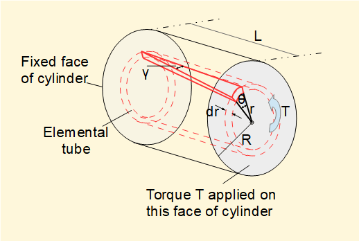
Consider the cylindrical section with radius R and length L shown below.

The rear face of the section is fixed and an anti-clockwise torque T is applied to the fromt face. There is an opposing reaction torque on the fixed rear face.
We consider an "elemental tube" inside the cylinder at radius r and width dr. Under the action of T the element twists and experiences shear strain γ. Correspondingly, the front face of the element twists through angle θ.


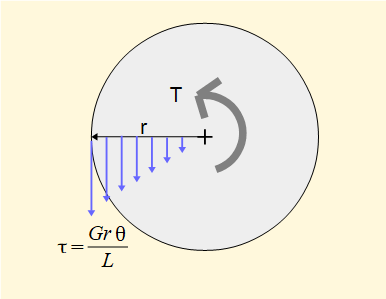
The diagram below shows the shear stress τ on the end face varies linearlly with radius r. τmax is at the outer surface of the cylinder.

In a previous tutorial we established a relation between bending moment M and normal stress σ for bending. We now do likewise of torque T and shear stress τ.
By equating the torque induced on the face of the cylinder by the shear stress to the applied torque it is shown that:


where J is the second polar moment of area about the central axis of a cylinder. Units of J are m4.
Digression (Note that the above integral is not the general definition of J, which is the double integral:


) to continue:


It can also be shown that the above relation applies to a hollow cylindrical shaft. For a hollow cylinder:

Normal stresses in torsion
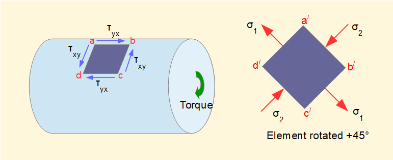
Consider in the diagram below a square element on the outer surface of a cylinder such that the top and bottom sides of the element are parallel to the axis of the cylinder. The cylinder is sbject to a torsional (torque) load.

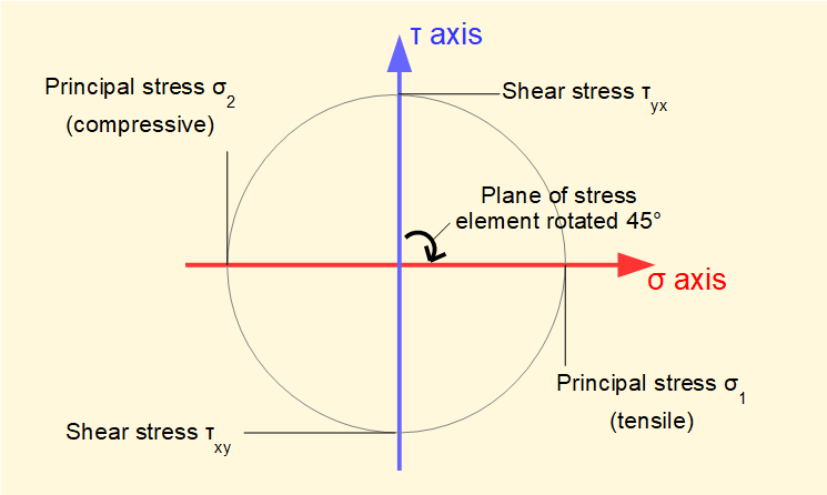
Stresses τ on the sides of this element τxy and τyx are pure shear (no normal stresses). This state is represented by the blue τ axis forming the base diameter of Mohr's circle (previous tutorial) shown below with τxy = τyx being the maximum shear stress.

Now consider the element rotated 45° such that a line d/b/ is parallel with the axis of the cylinder. This state is represented by the red σ axis forming the base diameter of Mohr's circle (remembering that rotation of the base diameter of Mohr's circle is twice the rotation of the stress element) which shows that σ1 and σ2 are principal stresses equal in magnitude to τmax. Tensile stress σ1 acts normal to faces b/c/ and a/d/ and compressive stress σ2 normal to faces a/b/ and d/c/.
A consequence of the principal stresses being on these planes is that a component subject to torsion and made from a brittle material will generally fail in tension at an angle of 45° to the longitudinal axis.
Next: Buckling of columns
I welcome feedback at: