In this tutorial we consider the mode of failure in structural columns known as buckling.
In general, columns are vertical structural members supporting a load from above in compression. Columns with cross-sectional dimensions significantly less than their height can fail by buckling, characterised by sudden lateral movement and a significant reduction in height. Buckling is normally associated with steel and timber columns. Concrete columns are generally too wide to experience buckling although measures are required to prevent buckling of internal steel reinforcement rods.
The theory developed below (known as Euler's theory) derives a critical load at which buckling occurs. The critical load varies depending on the method of fixing the column at the top and bottom ends. Note that the critical load can be significantly less than the load producing failure in simple compression.
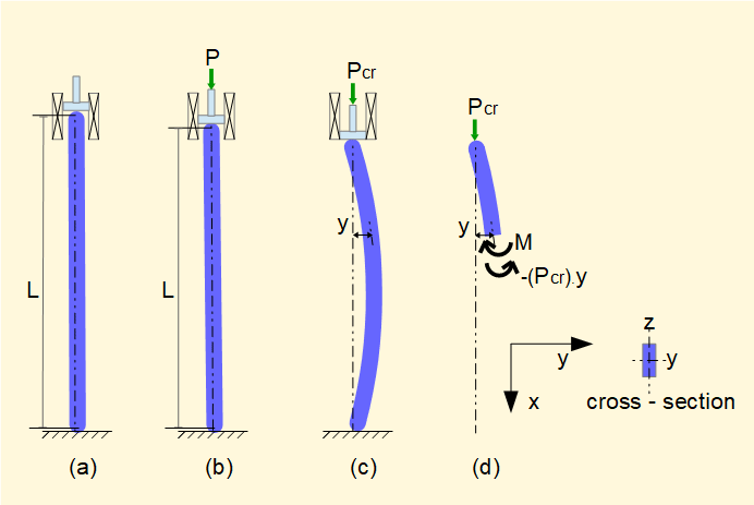
Consider a column with rectangular cross-section, length L which has pivoted or rounded ends top and bottom. We assume the column is perfectly straight and free from imperfections. (Axial displacements illustrated are greatly exaggerated.)

In (a) the column has no load applied. In (b) a force P is applied acting directly down the centroidal x axis with no eccentric loading. The column is subject to elastic strains under compressive stress but no bending occurs.
As P increases a critical point is reached (designated Pcr) where the column becomes unstable and jumps (buckles) to a state of equilibrium shown in (c). In this state the column is subject to bending moments M. (d) shows a free body diagram for this state at an arbitrary section where y = displacement of the centroidal x axis
The equilibrium condition for this section in terms of sum of moments = 0 is:
- (Pcr.).y ± M = 0
Now we have our well known dilemma concerning the sign of M. By the general convention for moments (Pcr.).y is -ve (anti-clockwise) thus M must be a clockwise moment (+ve}. However, by convetion the mode of bending is negative (relative to the defined axes) so we must consider M
as -ve.
Giving M = - (Pcr.).y ..... (i)
Note that if the column flexes in the -ve direction on the y axis the moment equation is the same.
We now refer to our tutorial on deflection of beams in bending where the following relation was establshed:


This second order differential equation is well known in mechanics as it has the same format as the equation defining simple harmonic motion. The solution is:

To determine the constants A and B we use boundary conditions where y = 0 at x = 0 and x = L.


The condition B = 0 and A = 0 represents the column undeflected.


This is the Euler column formula for a column with pivoted top and bottom supports.

This solution represents a half-sin wave form for the buckled column.
Other solutions for kL = 2π, 3π, etc. representing higher modes have no practical application since failure occurs at the fundamental mode.
Other end conditions
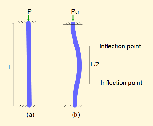
The Euler formula above applies to columns where both ends have pivot supports. Similar formulae can be derived for other end conditions. The diagram below shows the condition where both top and bottom supports are fixed.


The column assumes the form in (b) above with points of inflection as indicated. The central section has the same sinusoidal form as a column with pivot supports. It is seen that the critical load for fixed end conditions is four times that for pivoted end conditions.
Similar expressions for Pcr can be derived for other combinations of end conditions (e.g. one end fixed, one end pivoted) having the general expression:

For our examples Ke = 1 for pivoted ends and Ke = 4 for fixed ends.
This tutorial has provided a brief introduction to the behaiour of columns under load. It should be emphasised that the Euler column formula is based on an idealised model. There are several other criteria for design of columns based on alternative theories and experimental data.
Return to contents page for strength of materials
I welcome feedback at: