We devoted three previous tutorials to resolving by various methods the displacement, velocity and acceleration (the kinematics) of the elements in a slider and crank mechanism. In the following group of tutorials we examine the kinetics of the crank mechanism, that is the forces and moments arising in the individual elements and their consequences, in particular the output torque delivered to the crankshaft of an engine and unbalanced forces arising from inertial effects.
As an introduction in this tutorial we develop simple free body diagrams based on a static analysis, neglecting inertia, friction and gravitational forces, for slider and crank mechanisms with loading: (a) on an outward power stroke (as an engine) and (b) on an inward power stroke (as a compressor). In these contexts we use the term "piston" (enclosed in a cylinder) rather than "slider".
Free body diagrams
A free body diagram shows forces and moments acting on individual machine elements. For static equilibrium conditions sum of forces = 0 and sum of moments = 0. In a subsequent tutorial we show how inertia forces associated with acceleration of elements are included in static force analysis using D'Alembert's principle.
Example 1 - outward power stroke of an engine
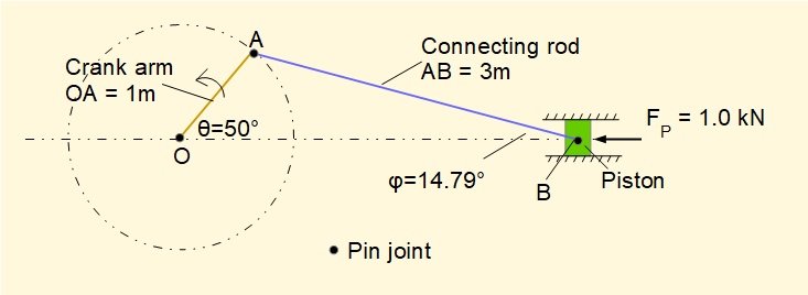
The figure below shows the outward* power stroke of a horizontal engine producing counter-clockwise rotation of the crank arm, shown at crank angle θ = 50°. Dimensions and other parameters are identical to examples in the kinematics tutorials with piston force FP added. The free body diagrams and calculated values of forces and moments are, of course, different for every crank angle over a complete cycle from 0°to 360°.
* For horizontal engines extremities of travel of the piston are known as inner dead centre (i.d.c.) at crank angle = 0° and outer dead centre (o.d.c.) at crank angle 180°. The corresponding terms for a vertical engine are respectively top dead centre and bottom dead centre. The notation for vertical engines is generally used for internal combustion engines regardless of their orientation. Note that a flipped image of this arrangement with piston on the left and crank on the right has clockwise rotation of the crank.
Drawing the diagrams
We draw free body diagrams for the three separate elements: piston, connecting rod and crank arm. The line of action of forces is taken through the centre of the pin joints. In this case we consider the pins simply as a means of transmitting forces between elements but they could be treated as individual elements with their own diagrams. In this instance the length of an arrow has no significance as regards magnitude of the force.
Diagrams for each element are shown below. The description which follows explains how the diagrams are constructed.
This degree of detail is intended for readers unfamiliar with free body diagrams.
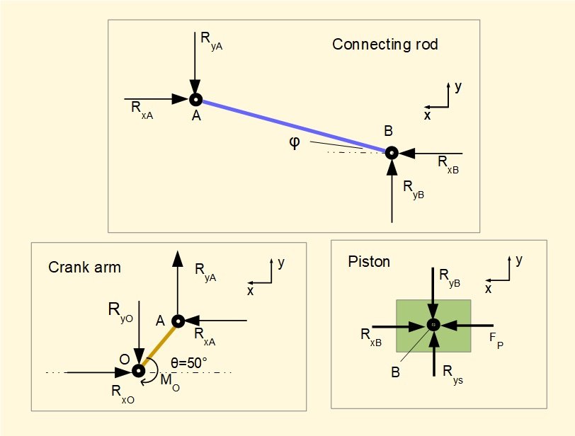
Starting with pin B linking the piston and connecting rod, we know the direction and magnitude of FP. The only other force acting on pin B is from the connecting rod with direction defined by angle φ. It is convenient to consider forces as components on x and y co-ordinates thus we designate forces from the connecting rod acting on the piston as RxB and RyB. In this instance directions of RxB and RyB can be assigned intuitively (the connecting rod exerts a horizontal force in a direction opposed to FP and a vertical force downward).
It follows (sum of forces on y axis = 0) that RyB is accompanied by an equal and opposite force RyS which is the reaction force applied from the cylinder wall to the piston. (We could continue by showing action and reaction forces between the cylinder mountings and ground but this is superfluous for our purpose). It is not always possible to draw the direction of a force using intuition, but as long as the given sign is in accordance with the co-ordinate axes, signs of calculated forces and moments will ultimately resolve correctly.
Because all forces on the piston act through a common point at pin B there are no moments to consider.
Moving to the diagram for the connecting rod, forces acting on the rod at pin B are equal and opposite to forces RxB and RyB acting on the piston. At pin A there are forces paired with the crank arm, designated RxA and RyA. As there are no other forces acting on the connecting rod, the directions of RxA and RyA must be opposed to RxB and RyB from the equilibrium conditions for forces in x and y directions.
The forces acting on the connecting rod are not directed through a single point hence moments must be considered, either moments of forces at pin A around pin B or vice versa, the choice is arbitrary (see below).
On the crank arm there are forces RxA and RyA at pin A equal and opposite to the forces on the connecting rod. At pin O there are forces RxO and RyO transmitted through crankshaft pin O. In engineering terms pin O is the crankshaft bearing journal. Because there are no other forces on the crank arm, directions of RxO and RyO are opposed to RxA and RyA.
RxA and RyA both generate a counter-clockwise moment about pin O. For the crank arm to be in static equilibrium a clockwise moment MO about pin O must be applied. Envisage MO as a clockwise "load torque" applied to pin O providing a reaction moment equal and opposite to the clockwise moment generated about O by RxA and RyA.
Equilibrium equations and calculations
It is good practice to place all terms initially on the LHS of the equations according to their sign as per the defined x and y axes. This ensures any wrongly assigned direction is highlighted when resolving the equations.
Piston
For Σ horizontal forces = 0 :
FP - RxB = 0 gives: RxB = FP = 1 kN --------- (1)
For Σ vertical forces = 0 :
RyS - RyB = 0 gives: RyB = RyS (the value of RyB is derived from equilibrium conditions for the connecting rod)
Connecting rodFor Σ horizontal forces = 0 :
RxB - RxA = 0 gives: RxB = RxA gives from (1): RxA = 1 kN -------- (2)
For Σ vertical forces = 0 :
RyB - RyA gives: RyB = RyA -------- (3)
For Σ moments = 0 :
We choose moments of forces RxA and RyA around pin B (counter-clockwise moments are +ve). RxB and RyB have no moment as they act through B.
From the geometry of the main diagram: RyA x AB.Cosφ - RxA x AB.Sinφ = 0
gives: (RxA x AB.Sinφ) = (RyA x AB.Cosφ) gives: RyA = (RxA x Tanφ)
gives from (2): RyA = 1000 x Tan(14.79°)
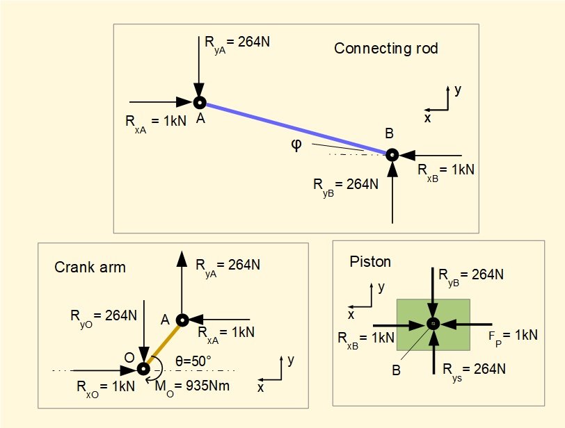
gives: RyA = 264 N --------(4) which from (3) gives: RyB = RyS = 264 N
Crank arm
For Σ horizontal forces = 0 :
RxA - RxO= 0 gives: RxA = RxO
from (2) gives: RxA = RxO = 1 kN
For Σ vertical forces = 0 :
RyA - RyO = 0 gives: RyA = RyO
from (4) gives: RyA = RyO = 264 N
For Σ moments = 0 :
Moments about O
RxO and RyO have no moment as they act through O.
(RxA x OA.Sinθ) + (RyA x OA.Cosθ) - MO = 0
gives: MO = (RxA x OA.Sinθ) + (RyA x OA.Cosθ) = (1000 x 1 x Sin(50°)) + (264 x 1 x Cos(50°))
gives: MO = 935 Nm
Calculated values for forces and moment are indicated on the diagrams below.
The following can be observed from the diagrams.
- At inner dead centre and outer dead centre positions (i.e. crank angles θ = 0° and 180°) all vertical forces at the pin joints are zero and action of all horizontal forces is through crankshaft pin O. Thus there is no moment around pin O. At these crank angles an engine produces zero torque.
- For a double-acting engine where the inward stroke is also a power stroke (crank angles from 180° to 360°) the direction of FP acting on the piston is reversed and consequently all horizontal forces on pin joints reverse. Vertical forces at pin joints do not reverse. Visualise the connecting rod reaction force pushing down on to the cylinder wall on the outward stroke and pulling down on to the cylinder wall on the inward stroke.
- Reversing the direction of rotation* of the crankshaft reverses angular positions of the crank arm and connecting rod symmetrically about the axis of the stroke on outward and inward strokes. For clockwise rotation the connecting rod exerts an upward force on to the cylinder wall on inward and outward strokes.
* In practice the direction of rotation of internal combustion engines is not reversible being determined by the fixed arrangement of fuel intake and exhaust valves. Steam engines can be reversed by adjusting the timing of steam inlet and exhaust valves by independent movement of the valve gear. - Forces transmitted along the crank arm and connecting rod can be resolved from the components of horizontal and vertical forces along the respective longitudinal axes as illustrated below. Forces are considered at pin joint B for the connecting rod and pin joint A for the crank arm. Pin joints A and O respectively could equally well be used. In this instance forces have been drawn to scale. At this crank angle net longitudinal forces in both crank arm and connecting rod are compressive.
Example 2 - inward compression stroke
The figure below shows the configuration for the inward compression stroke which could apply to a reciprocating gas compressor, the compression stroke of an internal combustion engine or a positive displacement pump. The crank angle in this example is 310°.
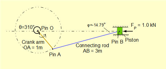
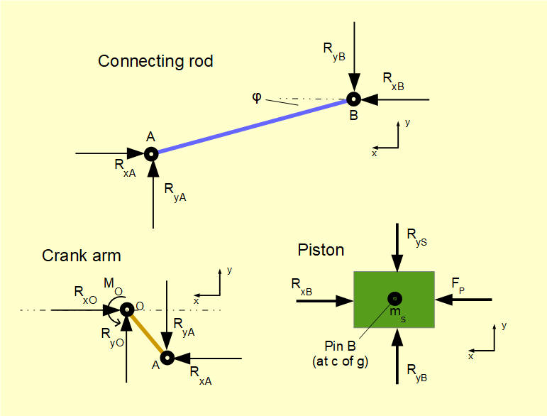
Free body diagrams for this configuration are shown below. Intuitively we visualise the connecting rod pushing upwards with the driving torque applied from the crankshaft, resulting in an upward force on the cylinder wall. Note that the "balancing" torque at crankshaft pin O required for static equilibrium is counter-clockwise.
Next: Crank mechanism - inertia forces and crankshaft torque
I welcome feedback at: