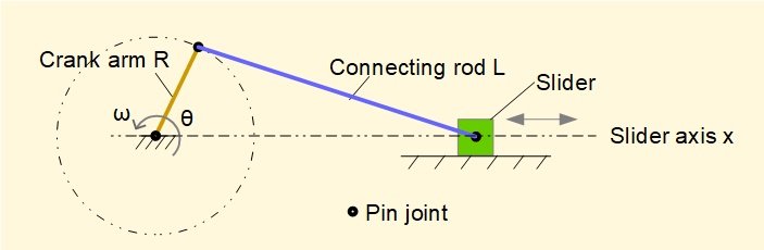
In two previous tutorials in this series we obtained values for velocities and accelerations in the slider and crank mechanism illustrated above by the following methods:
- from general expressions obtained by differentiating linear displacement of the slider with respect to time (differentiating once for velocity and twice for acceleration).
- from velocity and acceleration diagrams, by scaling directly from the diagram or by calculation from the geometry of the diagram.
In this tutorial we develop general mathematical expressions for velocity and acceleration of the slider using vectors. This approach provides insight into angular velocity and angular acceleration of the connecting rod when considered as vector quantities.
To recap from the previous tutorial we show below how relative velocities (and accelerations) are expressed as vectors. This relationship is the basis of the vector equations that follow.
Note that in this tutorial we change the convention previously used to designate quantities. Quantities denoted by a single subscript are assumed to be relative to "ground" frame of reference point O. Thus in this example va/o is designated va. Relative quantities are denoted as before with a dual subscript, for example vb/a is the velocity vector of point B relative to point A.
We now develop vector equations for velocity and acceleration for the generic crank mechanism shown below with crank arm length R, connecting rod length L, crank angle θ and angle φ the angle between the connecting rod and the slider axis. Angular velocity ω of the crank arm is constant.
Velocity vectors
The diagrams below shows velocity vectors vA, vB and vB/A. at pin joints A and B on the the slider and crank mechanism with crank angle θ = 50°. Note the corresponding vector diagram. If derivation of these vectors is unclear refer to the previous tutorial. Note also the directions chosen for unit vectors i and j
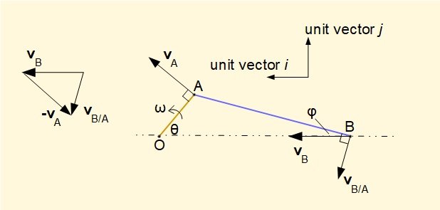
We can express vA, vB and vB/A in terms of unit vectors i and j as follows (taking particular note of signs according to the defined directions of unit vectors).
From the above we now develop equations for scalar values of vector velocities vB/A and vB for all crank angles θ using expressions for sin φ and cos φ in terms of sin θ derived in a previous tutorial, viz.
It can be shown that the expression for ||vB|| above is equivalent to that obtained in a previous tutorial by differentiation of displacement of point B with respect to time, viz.
as ||vA|| = ω.R and sin2θ = 2.sinθ.cosθ
The expression for ||vB/A|| is new and allows us to examine the characteristic of angular velocity of the connecting rod as vector ωAB through the crank cycle since ||ωAB|| = ||vB/A||.L
We use the example mechanism below as in previous tutorials.
The plot below shows ||ωAB|| the angular velocity of the connecting rod AB against crank angle θ for one crank cycle from the relation ||ωAB|| = ||vB/A||.AB computed from the derived expression for ||vB/A||.

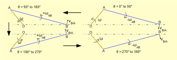
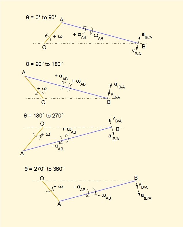
This plot shows the sign of ||ωAB|| changes at θ = 90° and θ = 270° during one revolution of the crank arm. The sign convention follows the right-hand rule for vector cross-product vt = ω x r (where vt is the tangential velocity). In this convention counter-clockwise rotation is positive and clockwise rotation is negative. r is the position vector of the rotating point relative to its centre of rotation, in this case point B rotating about point A. The diagrams below illustrate directions of ωAB and vB/A in each quadrant of rotation of the crank arm.
Acceleration vectors
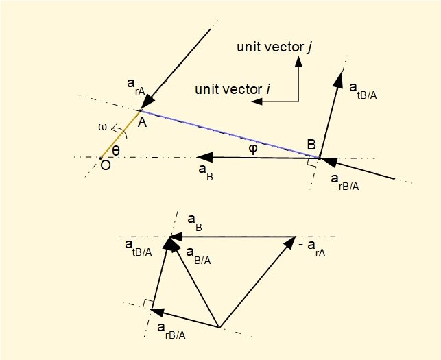
The diagrams below show:
- acceleration vectors arA, aB and aB/A (which is the vector sum of radial component arB/A and tangential component atB/A) at pin joints A and B on the slider and crank mechanism with crank angle θ = 50°. Because angular velocity ω of the crank arm is constant there is no tangential component of acceleration atA
- The corresponding acceleration diagram.
If derivation of these vectors is unclear* refer to the previous tutorial.
*To determine direction of vector atA/B we examine the plot for ωAB (see above). Crank angle θ is in the first quadrant where the plot shows ωAB (and hence vtB/A) decreasing in magnitude. Thus atB/A must oppose the direction of vtB/A.
It should be noted that an acceleration vector diagram can be constructed for any crank angle θ in the crank cycle.
The basic vector equation for the accelerations is: aB/A = aB - arA
For convenience, from this point on we will omit the subscript r indicating the radial component of aA.
We can express aA, aB and aB/A in terms of unit vectors i and j as follows (taking particular note of signs according to the defined direction of unit vectors).
It can be shown that the expression for ||aB || above is equivalent to that obtained in a previous tutorial by differentiation of velocity vB, viz.
The expression for ||atB/A|| is new and allows us to examine the characteristic of angular acceleration of the connecting rod as vector αAB through the crank cycle since ||αAB|| = ||atB/A||.L
Again we use the example mechanism below and the relationship between sin θ, sin φ and cos φ, noted above, viz.
The two plots below for show respectively ||atB/A|| the tangential acceleration of point B relative to point A computed from the derived expression above and angular acceleration ||αAB|| of connecting rod AB, both plots against crank angle for one crank cycle. The relationship between the two quantities is ||atB/A|| = ||αAB||.AB. This relationship in general terms is the vector cross-product at = α x r. As in the case of vt = ω x r, r is the position vector of the rotating point relative to its centre of rotation.
It is instructive to compare the plots of ||αAB|| and ||ωAB|| shown again above. The relationships for each quadrant of the crank cycle are illustrated in the diagrams below where validity of vector cross-products vt = ω x r and at = α x r are confirmed remembering that r is the position vector of point B relative to point A.
The table below provides an overview of crank angles θ over one crank cycle where absolute values of kinematic parameters vB, aB, ωAB and αAB are zero, positive maximum and negative maximum.
| Value of parameter | vB | aB | ωAB | αBA |
|---|---|---|---|---|
| zero | θ = 0° and 180° | θ identical to maximum values of vB | θ = 90° and 270° | θ = 0° and 180° |
| maximum (positive) | θ < 90° value dependent on ratio n | θ = 0° | θ = 180° | θ = 90° |
| maximum (negative) | θ > 270° value dependent on ratio n | two symmetrical points θ < 180° and θ > 180° values dependent on ratio n | θ = 0° | θ = 270° |
Next: Crank mechanism - free body diagrams
I welcome feedback at: