This is the first in a series of tutorials in the category Mechanics of Machines that examines slider and crank mechanisms.
The first three tutorials examine the kinematics of the slider and crank mechanism, i.e. displacement, velocity and acceleration of individual elements of the mechanism without reference to forces or torques, after which three tutorials examine the kinetics: these cover static analysis of forces and moments, inertia forces, crankshaft torque / effort and balancing. A further tutorial examines related topics of offset and eccentric mechanisms.
Traditional mechanical engineering studies favoured scaled graphical methods for analysis, for example Klein's diagram for crank mechanisms. This reflected design practice before computers were available. A disadvantage of graphical methods is that the underlying principles are not always clear. Also, a scaled diagram applies only to one position of the mechanism and must be repeated for every required position. Computers revolutionised mechanism design and analysis by carrying out complex and lengthy calculations for a complete range of input parameters.
There are several ways to obtain kinematic properties of the mechanism. The first approach (the subject of this tutorial) develops an expression for displacement of the slider from the geometry and then derives expressions for velocity and acceleration of the slider by successive differentiation of displacement.
The second approach uses velocity and acceleration diagrams constructed from known parameters. Unknown velocities and accelerations are then calculated from the geometry of the diagrams. The second tutorial explains this method.
In the third tutorial unknown velocities and accelerations are obtained from vector equations.
For these tutorials I assume the reader has a reasonable understanding of basic mechanics. In this tutorial I present the calculus in step-by-step detail as I know this is often an area of difficulty.
The diagram below shows the essential parts of a slider and crank mechanism. The slider, for example, can be a piston in a cylinder or a linear drive element in a machine. Thus the primary input is either a force applied to the slider or a torque applied to the crank arm. This is an in-line configuration where the linear axis of slider motion intersects the axis of rotation of the crank arm. This is not the case in an offset configuration which we consider in another tutorial.
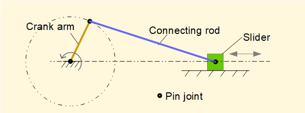
For the analysis we use the parameters defined in the diagram below.
- Crank arm ab has length R and rotates anti-clockwise with constant angular velocity ω about centre of rotation point a. Its position is defined by crank angle θ.
- Connecting rod bc has length L
- Slider pin joint point c is constrained to move along horizontal axis x:
x = 0 when crank angle θ = 0 - φ is the angle between connecting rod bc and the x axis
- Point d is the projection of point b on to line ac perpendicular to the x axis.
Our tasks are:
- Derive an expression for x (the horizontal displacement of slider c as a function of angle θ (the crank angle).
- Differentiate the expression from 1 with respect to time to obtain an expression for the velocity of slider point c
- Differentiate the expression from 2 with respect to time to obtain an expression for the acceleration of slider point c.
Derive an expression for x
Firstly note that the horizontal distance from point a to the origin at x = 0 is equal to (R + L).
Thus for any angles θ and φ x = (R + L) - (ad + dc) = (R + L} - (R.cos θ + L.cos φ) ................. (i)
We must transform the term (cos φ) to an expression in θ.
(As an approximation, textbooks often substitute an expression derived from power series for cos(φ) which simplifies subsequent differentiations. Nevertheless it is a good refresher for differential calculus to proceed with the original expression.)

This is the expression we set out to find for the horizontal displacement x of slider c as a function of θ.
It is useful as a check to compute the two values of x when the crank arm R is aligned with the connecting rod L, referred to in a horizontal crank mechanism* as inner dead centre (i.d.c.) and outer dead centre (o.d.c.), corresponding to crank angles θ = 0° and 180° respectively. (o.d.c. - i.d.c.) is the stroke of the mechanism. Stroke = 2R which is apparent from the geometry and confirmed by this check shown below.
* In a vertical crank arrangement the corresponding terms are top dead centre (t.d.c) and bottom dead centre (b.d.c). These terms are also used for all crank and piston operated internal combustion engines regardless of orientation.
The plot below shows displacement x against crank angle for one complete revolution of the crank arm computed from the expression above with n = 3 (R = 1m, L = 3m). A second plot for x = (1 - Cosθ) compares the derived expression with a sinusoidal form. Correspondence to a sinusoidal form increases as the ratio n increases.
Note the inherent characteristic of a crank mechanism that between θ = 0° and θ = 90° on the forward stroke and between θ = 270° and θ = 360° on the return stroke the slider travels significantly more than 50% of the stroke length.
Derive an expression for velocity v of slider c.

In this expression x is a function of variable θ (the crank angle). For velocity v of slider c we require the time derivative dx/dt for which we use the chain rule:

R and (in this case) ω are constants thus the differentiation becomes:
Taking the derivative with respect to θ of each term in the brackets:
d/dθ of constants 1 = 0 and n = 0
d/dθ of (- cosθ) = (+ sin θ)


The plot below shows velocity v against crank angle θ for one complete revolution of the crank arm computed from the expression above for ratio n = 3, (R = 1m, L = 3m) and ω = 2π radians/sec (60 revs/min).
Note that the maximum absolute velocities of the slider occur at crank angle θ < 90° on the outward stroke and at θ > 270° on the return stroke, not at the mid-way rotational position of the crank arm.
Derive an expression for linear acceleration a of slider c
To obtain an expression for the linear acceleration a of slider c as a function of crank angle θ we differentiate the expression for velocity v with respect to time again using the chain rule:


The plot below shows linear acceleration a of the slider against crank angle for one complete revolution of the crank arm computed using the expression derived above for ratio n = 3, (R = 1m, L = 3m) and ω = 2π radians/sec (60 revs/min).
Note the following:
- Acceleration of the slider is significantly higher at the inner dead centre (crank angle = 0°) than it is at outer dead centre (crank angle = 180°).
- Transitions between positive and negative accelerations are significant in the context of inertia forces (see a future tutorial)
- The twin negative peaks either side of the outer dead centre position arise from the combined effect of two separate components of acceleration, known as primary and secondary acceleration, corresponding to the two terms inside the brackets of the above expression. These components are significant when considering balancing of inertia forces (see a future tutorial).
Next: Crank mechanism kinematics - velocity and acceleration diagrams
I welcome feedback at: