Next: Thermodynamic cycles
I welcome feedback at:
In the previous tutorial we derived the following steady-flow energy equation for an open system in terms of fluid properties and conditions at infeed (position 1) and exit (position 2) with transfers of heat \(Q\) and work \(W\):
\({{Q} - {W} =({h_2}-{h_1}) + (\frac {1}{2}{C^2_2} - \frac {1}{2}{C^2_1}) + (g.{z_2} - g.{z_1})}\) -------- (1)
In this form \(Q\) and \(W\) are expressed in units \(\Large\tfrac{kJ}{kg}\).
Also note that the following conditions apply to the definition of a steady-flow system:
In this tutorial we apply the steady-flow energy equation to the following items of equipment and components under steady-flow conditions:
Boiler, Condenser, Nozzle, Diffuser, Turbine, Compressor, Throttle valve
The term boiler generally means a vessel for generating large quantities of steam at high pressure and temperature. Equipment items for releasing vapour at moderate or low temperatures from liquids and solids, typically used in refrigerators, chemical processes and food processing, are called evaporators.
Figure 1 is a generalised diagram of a boiler generating steam in an open flow system using a heating element in a pressure vessel.
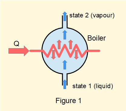
Considering equation (1) \({Q} - {W} =({h_2}-{h_1}) + (\frac {1}{2}{C^2_2} - \frac {1}{2}{C^2_1}) + (g.{z_2} - g.{z_1})\) for a boiler:
Thus the steady-flow energy equation for a boiler becomes: \(\bm{Q=({h_2}-{h_1})}\) ------- (3)
and since \(Q\) is positive, for a boiler \(h_2\) > \(h_1\)A condenser effects a change of phase from vapour to liquid, most commonly in steam power plants in conjunction with a boiler, turbine and boiler feed pump. Condensers are also widely used in process engineering.
Figure 2 is a generalised diagram of a condenser converting steam to water in an open flow system by means of a cooling element.
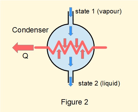
Consideration of equation (1) for a condenser is identical to a boiler thus the steady-flow energy equation for a condenser becomes:
\({Q=({h_2}-{h_1})}\)
As the value of \(Q\) for a condenser by convention is negative this becomes \(-(Q)=(h_1-h_2)\)
giving for the absolute value of \(Q\): \(\bm{Q=(h_1-h_2)}\) ------- (4)
with \(h_1\) > \(h_2\)
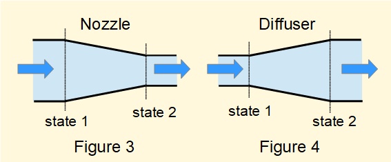
Figure 3 is a sectioned view of a convergent nozzle, namely a short length of pipe or duct where the area of the cross-section in the direction of flow reduces progressively.
Considering equation (1) \({Q} - {W} =({h_2}-{h_1}) + (\frac {1}{2}{C^2_2} - \frac {1}{2}{C^2_1}) + (g.{z_2} - g.{z_1})\) for a nozzle:
Thus the steady-flow energy equation for a nozzle becomes: \(0=({h_2}-{h_1}) + (\frac {1}{2}{C^2_2} - \frac {1}{2}{C^2_1})\)
giving: \(\bm{(\frac {1}{2}{C^2_2} - \frac {1}{2}{C^2_1})=({h_1}-{h_2})}\) ------- (5)
As a consequence of the continuity equation (2): \({C_2}>{C_1}\) thus for a nozzle \({h_1}>{h_2}\)
In general terms nozzles convert enthalpy \((h=u+p.v)\) into kinetic energy. In most applications* \({u_2}<{u_1}\), hence decreasing temperature, and \({p_2}<{p_1}\).
Figure 4 is a sectioned view of a divergent diffuser, namely a short length of pipe or duct where the area of the cross-section in the direction of flow increases progressively.
Consideration of equation (1) for a diffuser is identical to a nozzle with the form :
\((\frac {1}{2}{C^2_2} - \frac {1}{2}{C^2_1})=({h_1}-{h_2})\)
As a consequence of the continuity equation (2): \({C_2}<{C_1}\) and the steady-flow energy equation takes the form:
\(\bm{(\frac {1}{2}{C^2_1} - \frac {1}{2}{C^2_2})=({h_2}-{h_1})}\) ------- (6) thus for a diffuser \(h_2>h_1\)
In general terms diffusers convert kinetic energy into enthalpy \((h=u+p.v)\). In most applications* \({u_2}>{u_1}\), hence increasing temperature, and \({p_2}>{p_1}\).
(* for some conditions, such as supersonic flow, characteristics of fluid flow in nozzles and diffusers differ from those described above)
A turbine is a rotating machine that extracts work from fluid flowing from inlet to outlet, generally accompanied by expansion from high to low pressure.
Figure 5(a) shows a partial section of a typical arrangement of turbine blades mounted in circular arrays. Fixed blades act as nozzles directing fluid on to blades mounted on a disc attached to the output shaft (working turbines have multiple stages).
Figure 5(b) is a generalised diagram of a turbine in an open flow system.
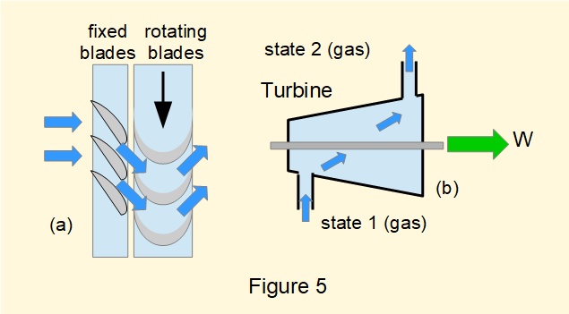
Considering equation (1) \({Q} - {W} =({h_2}-{h_1}) + (\frac {1}{2}{C^2_2} - \frac {1}{2}{C^2_1}) + (g.{z_2} - g.{z_1})\) for a turbine:
Thus the steady-flow energy equation for a turbine becomes:
\(-W=(h_2-h_1)\)
As the value of \(W\) for a turbine by convention is positive the equation becomes:
\(\bm {W=(h_1-h_2)}\) ------- (7)
which is consistent with \(h_1>h_2\) for an expansion process.
where: \(h_1=u_1+p_1.v_1\) and \(h_2=u_2+p_2.v_2\)
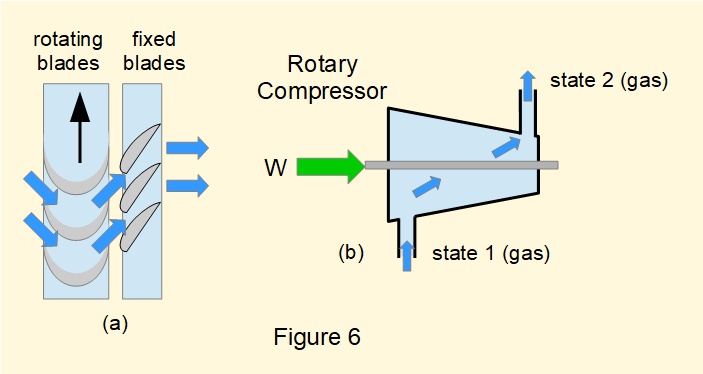
(i) Rotary compressor
A rotary compressor increases the pressure of a gas through the machine and is the inverse configuration of a turbine with work applied to the rotor.
Figure 6(a) shows a partial section of a typical arrangement. Rotating blades accelerate the incoming fluid which then flows through fixed blades configured as diffusers thus increasing the gas pressure.
Figure 6(b) is a generalised diagram of a rotary compressor in an open flow system.
Consideration of the steady-flow energy equation for a rotary compressor is identical to a turbine (see above).
Thus the steady-flow energy equation for a rotary compressor becomes:
\(-W=(h_2-h_1)\)
Since \(W\) for a compressor by convention is negative, this equation can be expressed in terms of absolute values of \(W\) as:
\(\bm{W=(h_2-h_1)}\) ------- (8)which is consistent with \(h_2>h_1\) for compression of a gas.
where: \(h_1=u_1+p_1.v_1\) and \(h_2=u_2+p_2.v_2\)
Reciprocating compressor
Figure 7 shows the general configuration of a reciprocating compressor which operates on a repeating cycle whereby gas is drawn in and then compressed by a piston moving in a cylinder synchronised with intake and discharge valves.
A reciprocating compressor can be treated as a steady-flow open system if cyclic pulsations at the discharge valve are smoothed by directing compressed gas to a receiver with a much larger volume relative to the cylinder**. Under this condition discharge from the receiver can be considered constant.
(** Figure 7 does not illustrate the difference in scale)
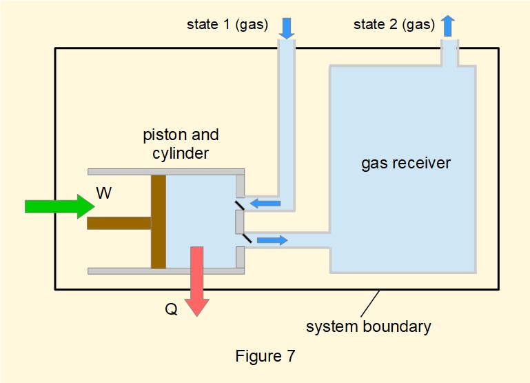
The steady-flow energy equation for a reciprocating compressor differs from a rotary compressor in that the process cannot be treated as adiabatic because the average flow velocity through the cylinder is relatively low. Figure 7 shows heat \(Q\) lost from the system
It can be assumed that \(C_1=C_2\) and the term \((g.{z_2} - g.{z_1})\) can be ignored.
Hence the steady-flow energy equation for a reciprocating compressor becomes:
\(Q-W=(h_2-h_1)\)
Since \(Q\) and \(W\) for a reciprocating compressor by convention are both negative, this equation can be expressed in terms of absolute values of \(Q\) and \(W\) as:
\(\bm{W-Q=(h_2-h_1)}\) ------- (9)
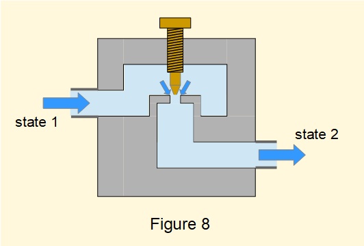
Figure 8 illustrates a typical throttle valve restricting fluid flowing in a pipe which causes a drop in pressure between inlet and outlet. In this example the size of the restriction can be varied by a thumb screw which changes the rate of flow through the valve. Throttling is generally applied where flow velocities are relatively low.
Considering equation (1) \({Q} - {W} =({h_2}-{h_1}) + (\frac {1}{2}{C^2_2} - \frac {1}{2}{C^2_1}) + (g.{z_2} - g.{z_1})\)
For the throttling process:
Thus the steady-flow energy equation for throttling becomes: \(\bm{h_1=h_2}\) ------- (10)
Given \((u_1+p_1.v_1)=(u_2+p_2.v_2)\) it follows that as pressure of a gas reduces across a throttle valve the specific volume increases. Changes of temperature, corresponding to changes of internal energy, can also occur depending on the properties of the gas.
A previous tutorial states the criteria for a reversible process in a closed system whereby a fluid passes through a series of equilibrium states with infinitesimal differences of external and internal temperatures during transfer of heat and infinitesimal differences of external and internal forces across moving boundaries during input and output of work.
Because fluid in a steady-flow process is in constant motion the concept of an infinite sequence of equilibrium states cannot apply. Viscous friction within a fluid and at its interface with the system boundary arising from the kinetic energy of flow increases its internal energy. This effect is irreversible.
Consequently criteria for hypothetical reversible steady-flow are stated as:
Next: Thermodynamic cycles
I welcome feedback at: