Kinematics of robot manipulators - Introduction
My tutorials generally cover mechanical engineering topics, pretty much as they were taught when I was a student in the 1960s. For a change I decided to tackle something which did not figure on the syllabus back then. Kinematics of robot manipulators is certainly in this category and I have put in the effort to acquire a reasonable understanding of the subject.
Consequently, please consider these "tutorials" more as study notes broadly at the level of the earlier stages of an undergraduate course. My sources are primarily video lectures and other material online. In particular I am pleased to acknowledge (and recommend) the following which have been particularly useful. However, all explanatory text and diagrams are my own composition.
https://modernrobotics.northwestern.edu
Linear transformations in matrix form are the principal underlying maths in this series of tutorials. Again, this was not mainstream for mechanical engineers fifty years ago. To get up to speed in linear algebra I highly recommend Prof. Gilbert Strang's lectures and course material on MIT's open access programme.
Linear Algebra | Mathematics | MIT OpenCourseWare
Robot basics
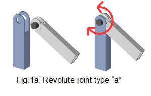
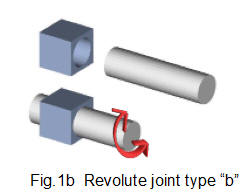
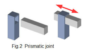
Industrial robot manipulators comprise, for the most part, a number of rigid bodies (which we will call links) connected in series* by joints which allow relative motion between two links. In these tutorials we consider only two types of joint** - revolute shown in Figs 1a and 1b, which has one rotational degree of freedom and prismatic shown in Fig 2, which has one linear degree of freedom. The two types of revolute joint are distinguished by the orientation of the axis of rotation relative to the axis of the link. If a manipulator has n joints each joint having one degree of freedom it is said to have a total of n degrees of freedom.
* another category of robots has links connected in parallel
** other types include spherical and universal joints which have more than one degree of freedom. These joints are often used in the gripping part of the manipulator, known as the end effector.
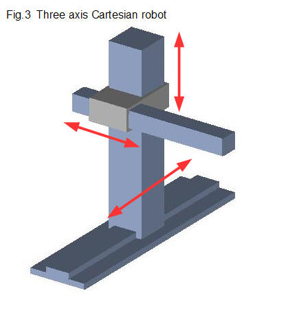
Robot manipulators have different combinations of links and joints. Fig. 3 shows a manipulator where all the joints are prismatic, known as a Cartesian robot.
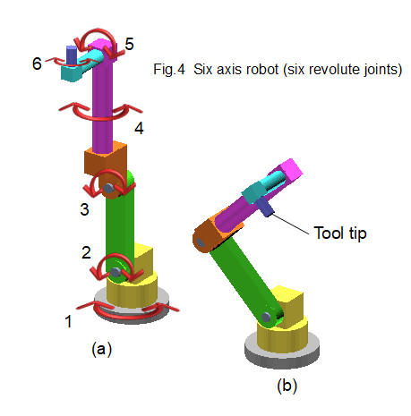
Fig. 4 shows a robot manipulator, generally known as a six axis robot, with six revolute joints which is widely used for industrial applications. The kinematic analysis in the following tutorials is based on this robot model. The base (grey colour) represents ground. For clarity each link is illustrated in a separate colour. Revolute joints #2 and #3 are type "a" and joints #1, #4, #5 and #6 are type "b" as shown in Figs.1a and 1b. The actuators that move the links (in most cases electrical servo or stepper motors) are not shown. The outer extremity of the final link is called the tool tip and is the point of attachment of the end effector, for example a gripper or paint spray nozzle. The end effector itself might have additional joints but these are not included in our analysis.
Fig.4(a) shows the robot in a vertical extended position. This is the datum point for kinematic analysis in the next tutorial. Fig.4(b) shows the robot in a specific working pose. We use this pose as the end point for kinematic analysis.
Kinematic analysis
Kinematics is the study of the motion of a rigid body* without reference to forces acting on the body. It is concerned with determining the position (often called displacement), velocity and acceleration of a body. In these tutorials we are mainly concerned with finding the position of each robot link for a particular position of the tool tip. This position is often referred to as the tool tip pose.
* More precisely kinematics considers the motion of particles from which the motion of rigid bodies is deduced.
We can approach this task in two ways. In forward kinematics, we set the angle of each revolute joint (and the linear displacement of any prismatic joints) and then compute the position of the tool tip. In inverse kinematics we set the position of the tool tip and then compute the required angle (or displacement) of each joint. For practical applications inverse kinematics is more useful, but more complex, so in the first two tutorials we examine forward kinematics.
I welcome feedback at: