Crank mechanisms
Offsets and eccentrics
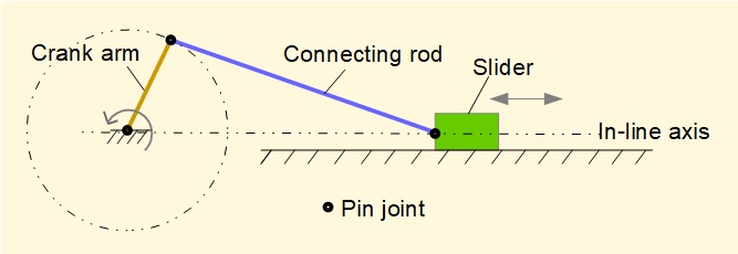
This series of tutorials covering kinematics and kinetics of the crank and slider mechanism is based on an in-line configuration of crank and slider where the linear axis of slider motion intersects the axis of rotation of the crank arm as shown below.
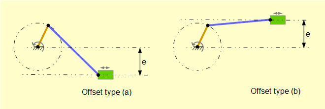
An offset configuration where the linear axis of the slider does not intersect the axis of rotation of the crank arm arises in some applications. Two offset configurations are shown below defined by relative positions of the respective axes. Displacement of the respective axes, e, is termed the eccentricity. Type (a) is sometimes stated as "positive eccentricity" and type (b) as "negative eccentricity" but I avoid these terms because they presuppose a specific orientation of reference axes.
We now apply the analytical method used in a previous tutorial for in-line configurations. Consider the diagram below for offset type (b) with the crank arm R at an arbitrary crank angle θ.
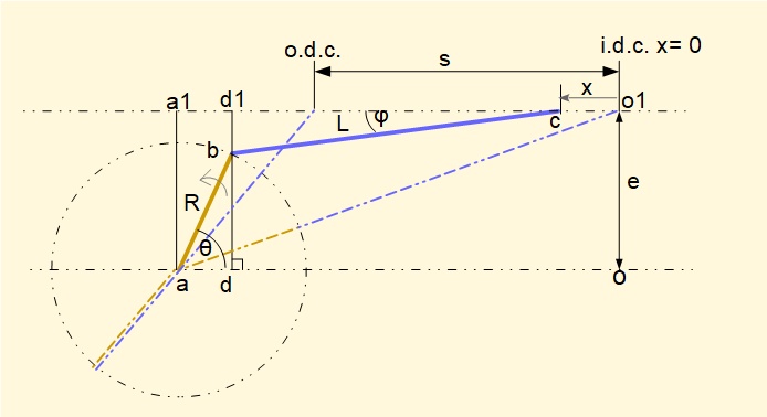
- Crank arm ab has length R and rotates anti-clockwise with constant angular velocity ω about centre of rotation point a. Its position is defined by crank angle θ.
- Connecting rod bc has length L
- Point o is the origin of the co-ordinate axes
- φ is the angle between the connecting rod and the slider axis
- Point d is the vertical projection of point b on line ao
- a1, d1 and o1 are vertical projections of points a, d and o on the slider axis.
- e is the eccentricity of the slider axis.
Positions of inner dead centre (idc) and outer dead centre (odc) on the horizontal slider axis which determine stroke s are defined by the two collinear positions of crank arm R and connecting rod L indicated by dashed lines. Note that these positions do not occur at crank angles 0° and 180° respectively as is the case for the in-line configuration.
Derive an expression for x
The task is to derive an expression for displacement x of the slider in terms of crank angle θ, represented by point c measured from the idc position . The method is identical to that for an in-line configuration in a previous tutorial.

also ao = a1o1 a1d1 = ad =Rcosθ d1c = Lcosφ

We must transform the term (cos φ) to an expression in θ.
note that e = (db + bd1 ) = (Rsinθ + Lsinφ) thus Lsinφ = (e - Rsinθ)
substituting for cosφ in equation (1) gives:
We now have an expression for the horizontal displacement x of slider c as a function of θ. The plot below shows displacement x against crank angle θ for one complete revolution of the crank arm computed from the expression above with n = 3 and R = 1m, L = 3m for a range of eccentricities e from 0 to 1.8 m.
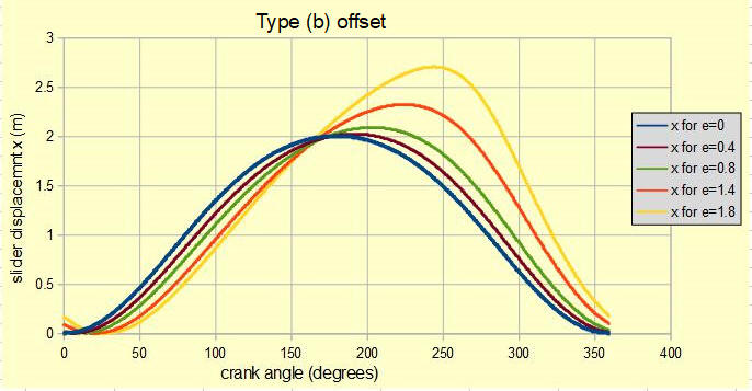
From the plots it can be seen that stroke increases with increasing eccentricity. A limit is reached when e > (L - R); crank rotation is not possible beyond this limit. In this example (L - R) = 2m which is the upper limit of eccentricity.
With offset It is also seen that the forward stroke from idc to odc occurs over a larger crank angle than the reverse stroke, the effect increasing with greater eccentricity. For example, for e = 1.4 crank angles at idc and odc are c. 20° and 230° respectively. Thus the crank angle of the forward stroke spans c. 210° and that of the reverse stroke c. 150°. This provides a quick return mechanism with practical applications in machinery.
Note that the above plot is for offset type (b) (defined above) where the slider axis is above the axis of rotation of the crank arm. In contrast the plot below shows displacement x for offset type (a) where the slider axis is below the axis of rotation of the crank arm for e = 1.4.
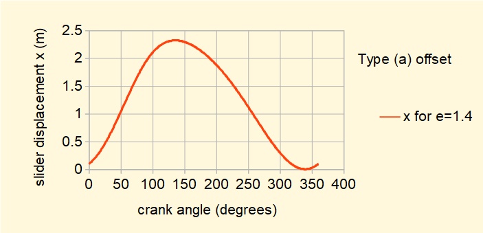
In this configuration the displacement plot of type (b) is reversed in that the forward stroke is "fast" and the reverse stroke is "slow."
Derive an expression for velocity v of slider c.

In this expression x is a function of variable θ (the crank angle). For velocity v of slider c we require the time derivative dx/dt for which we use the chain rule:

The method for obtaining derivative dx/dt for the above expression is identical to that in the tutorial for in-line configurations and it is not necessary to repeat the steps here.
The derived expression is:
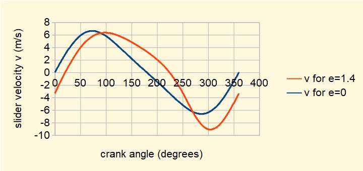
The plot below derived from this expression shows slider velocity against crank angle for the type (b) offset mechanism defined above with e = 1.4 compared with the in-line configuration (e = 0). The "quick return" characteristic is clearly illustrated. Note also zero velocity at idc and odc.
I will leave the next differentiation to find an exxpression for acceleration dv/dt for a rainy day!
Eccentric crank mechanism
An eccentric is a special configuration of a crank mechanism shown in the figure below in the form of a slider and crank.
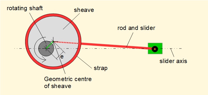
A disc called a sheave is fixed to a shaft such that the centre of the sheave is eccentric to the shaft (e on the diagram). A strap is placed around the circumference of the sheave and is free to rotate. Typically a rod or lever arm is rigidly fixed to the strap. When the shaft rotates, the sheave acts like a cam on the strap producing reciprocating motion on the rod. In the configuration above a slider attached to the end of the rod is constrained to move on a horizontal axis. The motion of this slider is identical to an in-line slider and crank mechanism with crank arm length e and the connecting rod equivalent to the distance from the centre of the sheave to the pin joint of the slider. The slider axis can equally well be offset from the rotational axis of the shaft.
The diagram below shows the cycle for a complete revolution of the shaft at crank angles 0°, 90°, 180° and 270°.
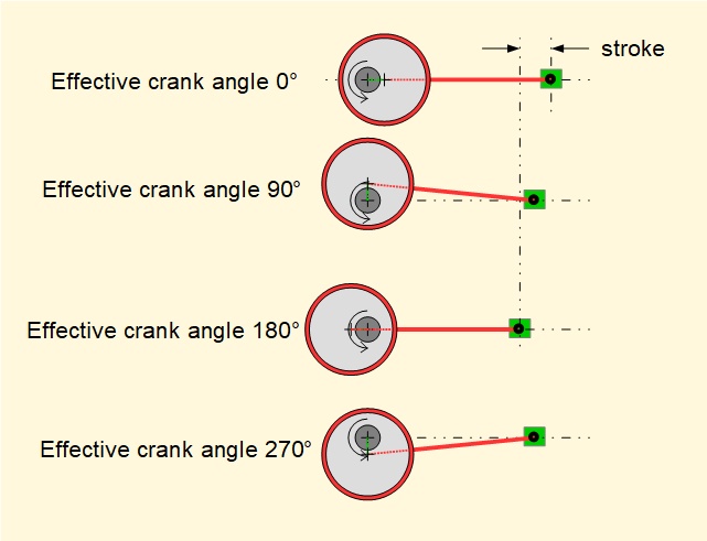
The relatively small effective crank arm provides a correspondingly short output stroke. Eccentrics were particularly useful in steam engines providing reciprocating drives from the main crankshaft to valve gear and auxiliaries such as a water pump . Note that eccentrics can only convert rotational motion to reciprocating motion. A force acting on to the strap from a rod or lever arm cannot drive the shaft.
I welcome feedback at: